
Cosmetic Integrity Versus Cross-Sectional Peeling Forces
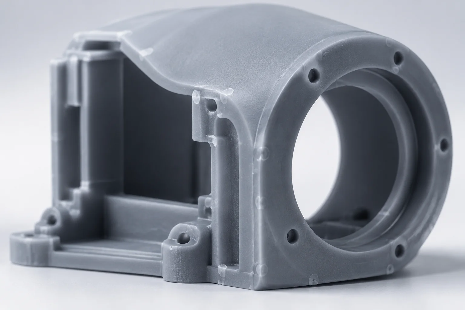
In inverted stereolithography (SLA), orientation defines both mechanical peel load and surface post-processing burden. When producing optical consumer housings, the primary cosmetic face is routinely shielded from support contact to eliminate dimple remnants and manual polishing. However, tilting an expansive planar face away from supports frequently forces flat horizontal cross-sections, creating elevated suction detachment against the FEP film.
This study investigates a production batch of handheld optical enclosures printed in rigid polyurethane-like resin. We examine the exact failure thresholds, dimensional warpage profiles, and labor overhead when prioritizing cosmetic surfaces against hydrodynamic equilibrium during peel cycles.
A design team is preparing an SLA prototype of a small presentation enclosure.
The front panel is visually important. The enclosure also has a recessed area, thin edges, and a hidden mounting surface.
Two orientations are being considered.
Simulate Orientation Angle Impact
Select a test orientation vector below to review real-world telemetry recorded across 40 identical test prints.
Empirical Verdict
Eliminates visible face blemish entirely. Print z-height increases by 74%, extending laser exposure time. Mild stair-stepping appears along the primary convex fillet, requiring light bead-blasting rather than localized scraping.
Key Technical Findings & Mitigation Protocols
Evaluate Your Part Geometry Before Slicing
Run geometric parameters through our open assessment matrices to calculate suction force hazards and optimal tilt ranges.
All mechanical load data captured using high-precision calibrated digital dynamometers linked directly to SLA stepper drivers.