Stereolithography Risk Modeling

Surface Defect Probability Matrix

Evaluate the empirical probability of peel lines, surface pitting, and contact scarring across varying inclination angles before generating supports.

SLA / DLP / LCD Angular Risk Mapping ISO/ASTM 52900 0.025 - 0.100 mm Layers
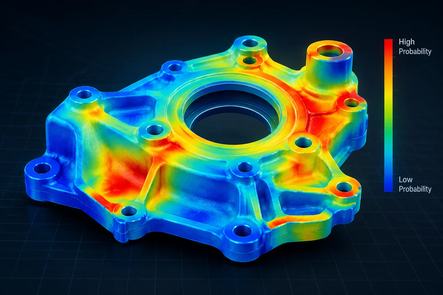
Technical heat map showing risk distribution of surface defects on angled 3D model

Analytical Overview & Geometric Risk Zones

In stereolithography additive manufacturing, orientation relative to the vat membrane dictates hydrodynamic shear, peel separation force, and local layer displacement. Flat horizontal geometries perpendicular to the optical axis experience high suction force during vat separation, which elevates peel line frequency and mechanical warping risk. Conversely, steep inclinations approaching vertical alignment reduce individual cross-sectional surface areas, shifting vulnerability away from peel shock toward stair-stepping striations and unsupported overhang droop.

This probability matrix classifies surface vulnerabilities into three critical zones: low angles (0°–25°) characterized by intense peel tension and severe contact scar pitting; moderate transitional angles (30°–55°) offering optimized balance between print stability and cosmetic integrity; and steep angles (60°–90°) where layer staircase visibility peaks while detachment probability drops significantly. Slicing technicians can align functional planes to mitigate defect clusters.
Risk Breakdown by Angular Inclination

Detailed matrix records evaluate surface degradation mechanisms across primary orientation intervals. Select an angular sector below to examine failure modes, defect probabilities, and recommended remediation protocols:

High Risk: Suction Force & Heavy Support Scarring

Angles under 25 degrees present elevated probability of severe peel defects and noticeable surface pitting. Large cross sections generate strong vacuum suction against the flexible vat film during peel cycles.

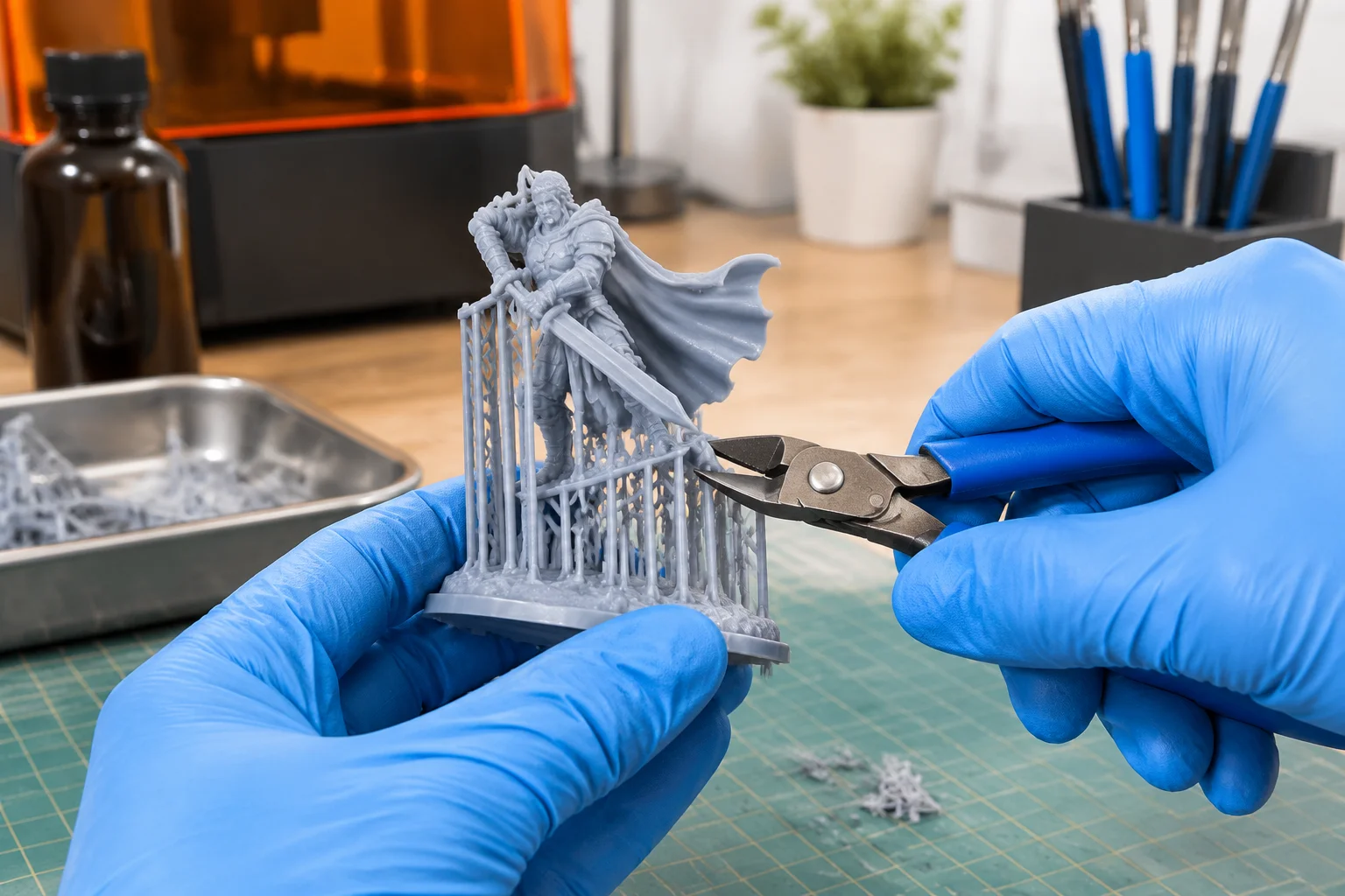
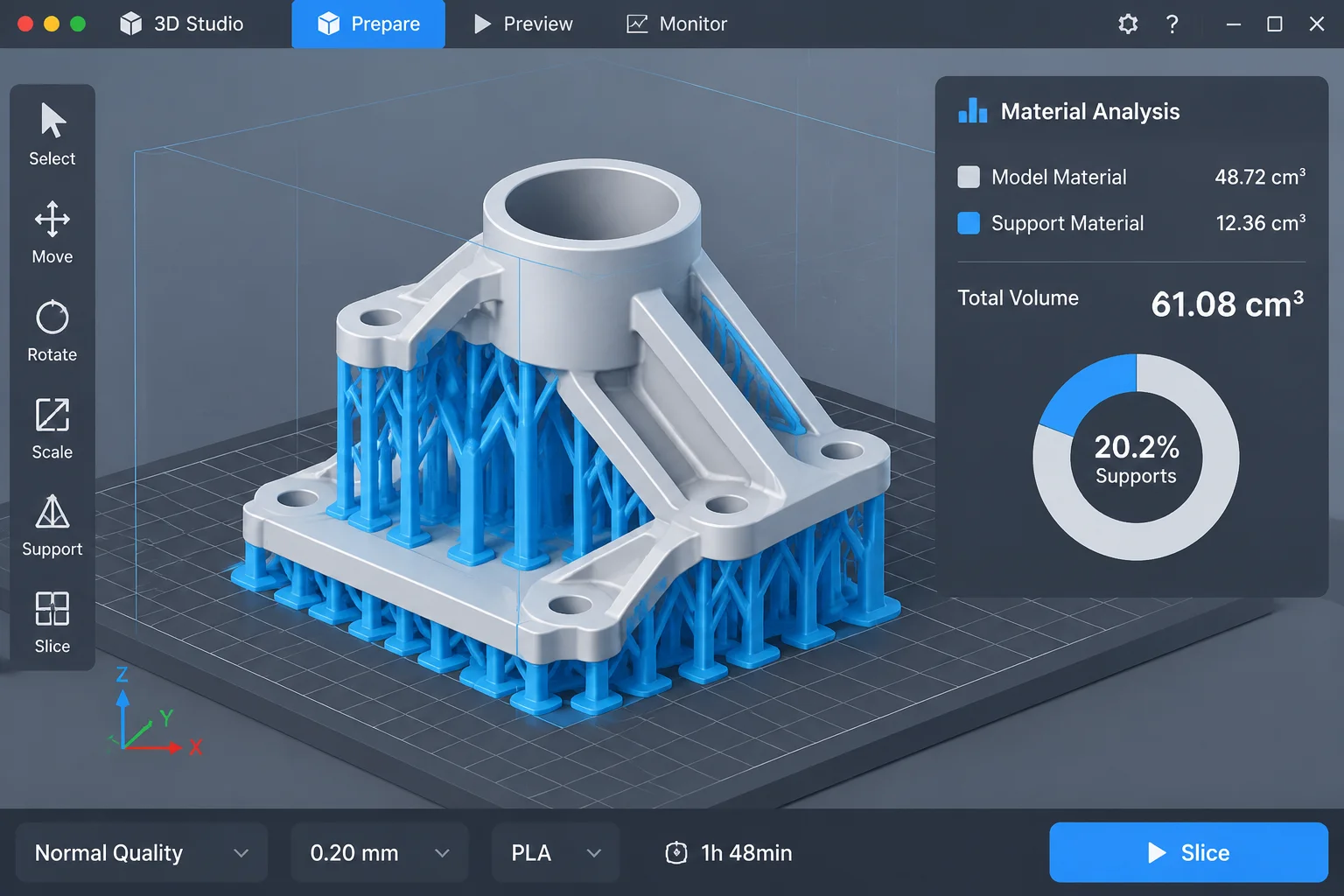
  • High density of heavy support touchpoints required, leaving deep scars and cratering across cosmetic faces.
  • Pronounced peel lines and micro-delamination from mechanical pull forces on freshly cured green-state resin layers.

Matrix Technical Specifications

Evaluation Standard ISO/ASTM 52902 Benchmark Geometry Protocol
Compatible SLA Materials Standard, Tough, Rigid, Castable Wax & Clear Resins
Critical Threshold Angle 32.5° (Mean Self-Supporting Boundary at 50 μm)
Scar Depth Deviation 0.05 mm – 0.28 mm depending on tip diameter

Request Matrix Integration & Raw Dataset

Access our complete technical dataset containing empirical testing across 48 orientation angles, viscosity correlations, and algorithmic touchpoint compensation tables for your laboratory.

Frequently Asked Inquiries

Engineering Diagnostics

Eliminate Surface Defects Before Printing

Integrate standardized orientation guidelines into your engineering workflow to preserve critical aesthetic and functional surfaces.