An empirical analysis of the November 2026 Insider pre-computation pipeline: inspecting foundation layer transitions, mesh consolidation, and raft contact dynamics before execution.
Clarissa MaoNovember 18, 20267 min read
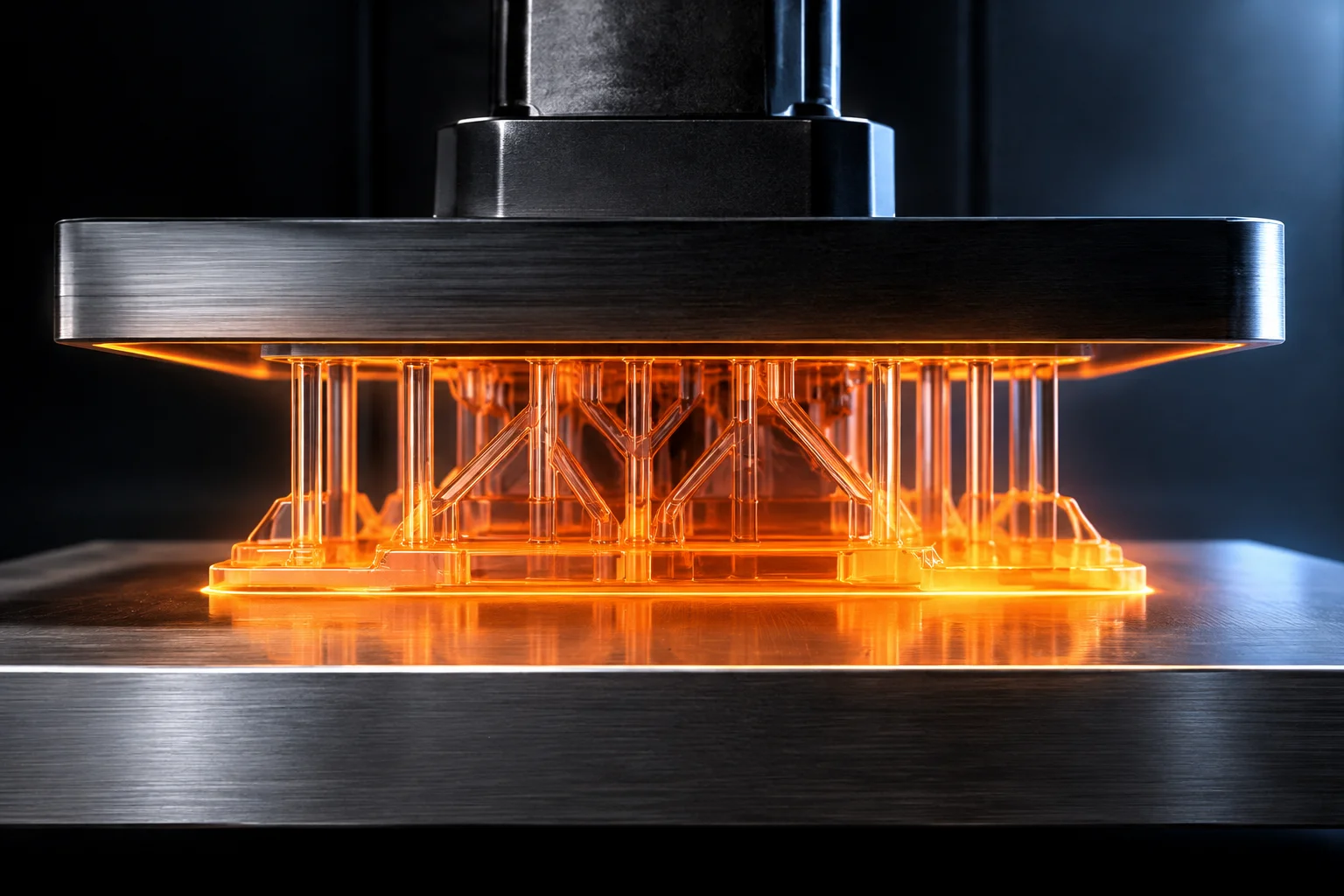
Digital cross-section rendering demonstrating early layer merge gradient between the base raft and support pillar roots.
01
Mechanics of Early Layer Geometry Merging
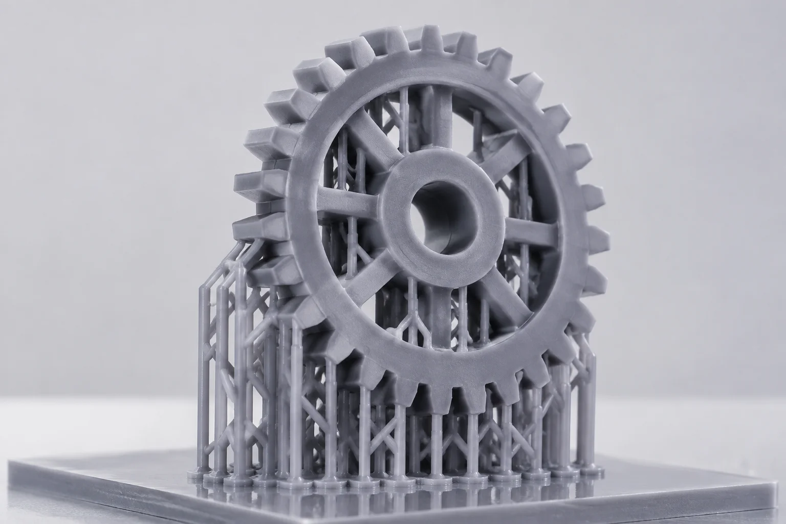
During initial layer synthesis in stereolithography, the transition zone between high-exposure foundation layers and delicate support pillars presents severe volumetric gradients. When photopolymer resin transitions through extended exposure times—often exceeding ten to fifteen times the normal layer duration—the surrounding liquid undergoes rapid thermal expansion and radical diffusion. Without precise spatial merging preview tools, slicing engines frequently approximate pillar footings as boolean unions, obscuring subtle step-offs and overcured lip expansions.
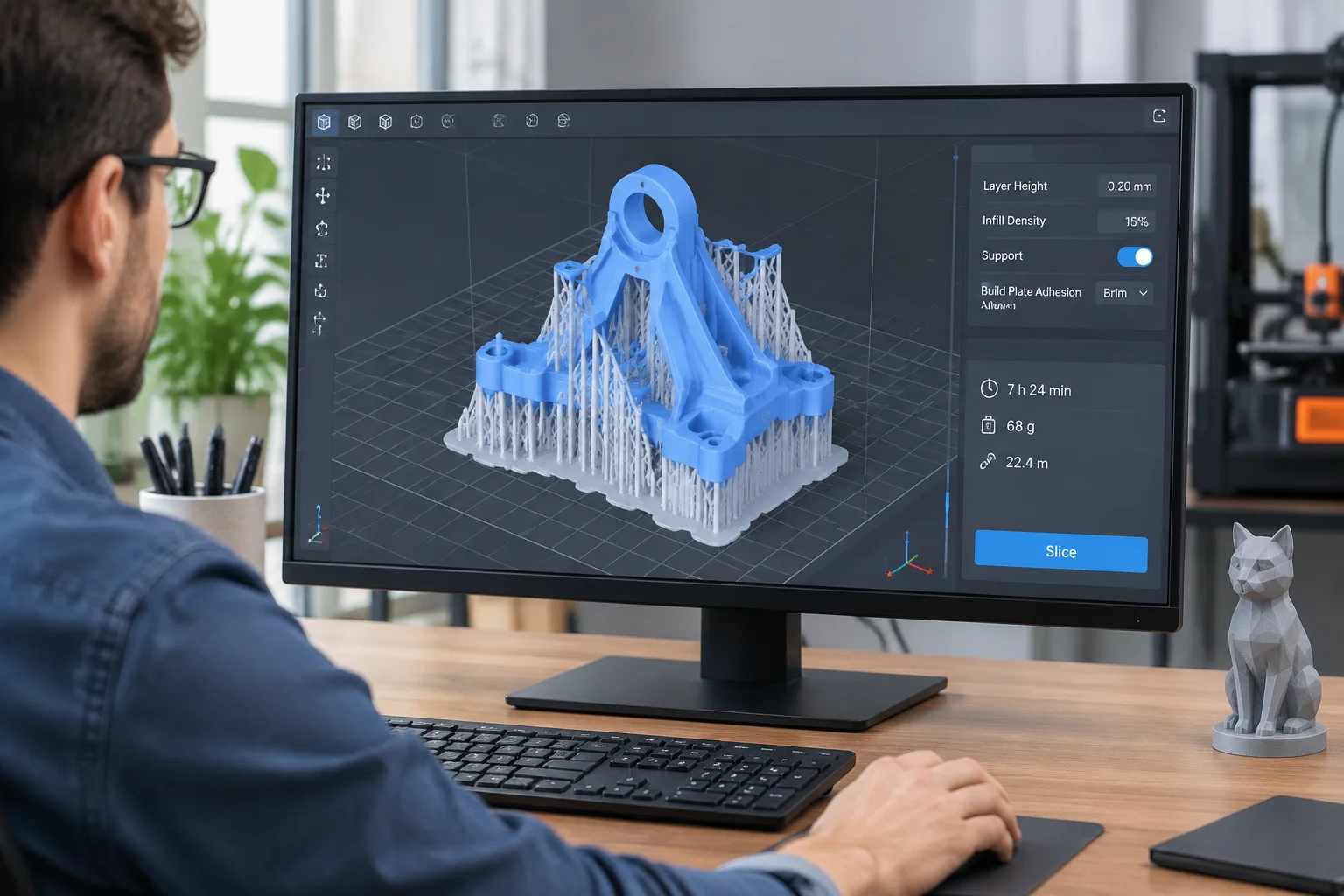
The November 2026 Insider update introduces an explicit mesh interpolation preview, resolving how foundation rafts mathematically unify with secondary support lattices. By visualizing the true computed boundary rather than an idealistic CAD union, engineers detect premature bridging, unvented micro-voids, and excessive footing flaring before committing vat resources.
Visualizing early layer merging transforms bottom-end adhesion from a guessing game into an inspectable geometric boundary, preventing separation failures before the laser strikes.
— Clarissa Mao, Senior Slicing Architect
02
Critical Boundary Conditions and Diagnostics
Analyzing early merge behavior requires tracking distinct geometric artifacts across the initial fifteen layers. In complex dental bases and dense industrial array clusters, standard automatic supports often place contact stems too close to raft taper boundaries. Observing these layers in isolation highlights where excessive material consolidation can distort vertical accuracy.
Raft perimeter step-down visualization confirms uniform 45-degree chamfer relief to avoid razor-edge peel force spikes.
Dynamic color-mapped cure gradients identify where scattered UV dosage merges adjacent support stems into unintentional solid monoliths.
Internal micro-pocket diagnostics automatically flag pockets below 0.35 mm trapped between the platform surface and ascending trusses.
03
Best Practices for Verification Workflow
Preparing intricate fixtures demands systematic layer-by-layer inspection. Operators should enable the early merge preview filter, isolating layers 1 through 20 under 2.5x viewport zoom. Verify that the transition layers maintain smooth, monotonic cross-sectional volume reduction rather than erratic step changes.
When individual support touchpoints collide with the foundation slope, shift pillar anchors inward or raise base lift height by at least 1.2 mm. This separation prevents the heavy exposure footing from encroaching onto delicate component margins, maintaining pristine dimensional clearance across the lowest assembly surfaces.
04
Frequently Asked Questions
Heavy burn-in cure cycles cause light bleeding that fuses closely spaced support stalks into single brittle blocks. Previewing early layer merge geometry allows operators to spot overlapping exposure boundaries and widen stem spacing prior to printing.
The calculation runs asynchronously via Vulkan viewport shaders, adding negligible overhead during regular layer scrubbing while rendering accurate boundary simulations in real time.
When printing directly onto the platform, the preview highlights elephant foot flaring and cross-sectional expansion across the initial burn-in layers, clarifying exactly where dimensional offsets need compensation.
Keywords:SLA SlicingLayer MergeGeometry Preview
Engineering Evaluation
Calculate Layer Peeling & Base Separation
Benchmark your support density against vat peeling mechanics with our automated risk tools.