Analyzing the critical relationship between tip diameter, peel force dynamics, and cosmetic preservation to prevent pitting and part distortion during SLA printing.
James HoldenNovember 15, 20266 min read
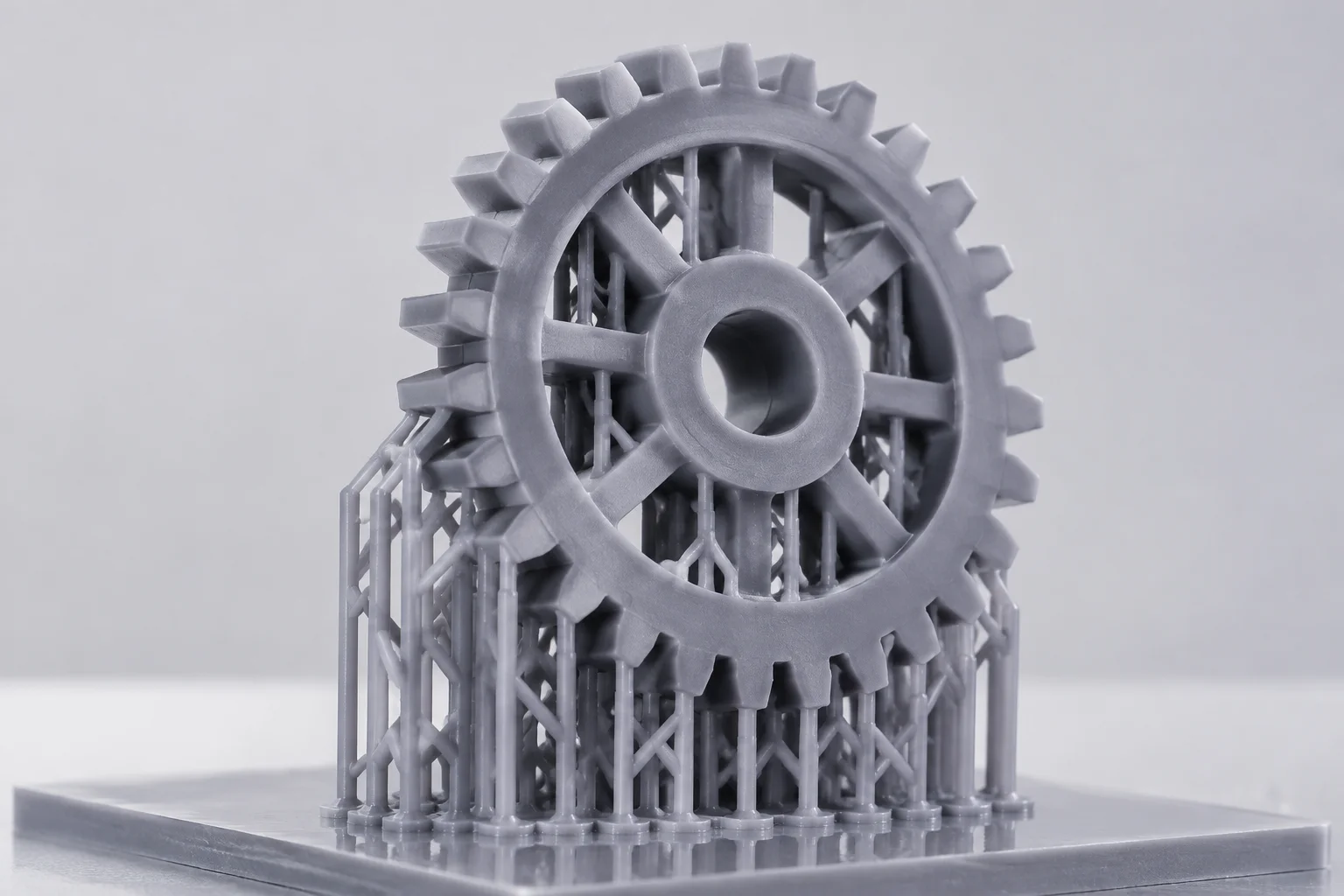
Macro view of fine support contact points distributed along the overhang boundary of a precision mechanical test piece.
01
Mechanics of Contact Geometry and Separation Dynamics
In stereolithography (SLA) additive manufacturing, contact points define the exact boundary where sacrificial support trusses meet the component surface. During every layer transition, the vat mechanism separates the newly cured resin plane from the release film. This peel movement exerts intense vertical tension across every support tip. When contact cross-sections are scaled down to reduce surface marks, the local tensile load escalates rapidly.
When that load exceeds the green-state tensile strength of the photopolymer, the junction tears apart mid-cycle, leaving unsupported islands and distorted geometries. Conversely, excessively broad contact points anchor the part securely but transfer substantial peeling energy into thin sidewalls, producing localized planar warpage. Balancing this mechanical load against allowable surface scarring requires treating contact point sizing as a deliberate structural design parameter.
Trimming contact point diameter by merely 0.15 mm cuts finishing labor significantly, but shifts the mechanical failure boundary directly onto green-state layer adhesion.
— Technical Tooling Research Group, 2026
02
Touchpoint Diameter Selection by Geometric Priority
Applying identical contact diameters across an entire model compromises either structural reliability or surface quality. Sophisticated orientation workflows divide support geometry into three functional categories:
Primary anchor points (0.70 mm to 0.90 mm): Assigned strictly to the lowest initial islands and massive bulk sections where suction resistance during early layers demands maximum mechanical grip.
Body stability arrays (0.45 mm to 0.60 mm): Positioned along recurring overhang tiers and lateral ribs to maintain true spatial position against resin crossflow currents.
Detail and cosmetic margins (0.25 mm to 0.35 mm): Dedicated to fragile perimeter curves, sharp edges, and cosmetic faces to allow effortless pre-cure snap removal without leaving craters.
03
Preventing Craters, Surface Pitting, and Tear-Out
Surface pitting takes place when the shear plane of a support tip sinks below the nominal outer contour of the part. This defect stems from excessive tip penetration into the CAD mesh combined with an aggressive truss taper. When tips penetrate beyond 0.20 mm, the photopolymer curing exposure merges the support joint directly into the outer skin layers, eliminating any distinct cleavage point.
Maintaining tip penetration between 0.08 mm and 0.15 mm paired with a uniform 45-degree taper forces the failure plane to form cleanly at the touchpoint waist. Detaching supports while the print remains in its green state—before secondary UV light treatment or thermal post-curing—dramatically lowers the force needed for separation. This sequence prevents brittle fractures from chipping into functional geometries.
04
Frequently Addressed Practical Inquiries
Flexible and elastomeric resins need larger contact tips ranging from 0.65 mm to 0.85 mm because elastic deformation absorbs peel energy and risks premature tearing. Viscous engineering resins also benefit from sturdier junctions to counter fluid drag during platform lift cycles.
Indented hollows appear when support struts are removed after final UV curing when resin reaches full brittleness, or when excessive software penetration causes the fracture line to propagate into the part body. Removing supports in the green state leaves minor proud bumps that are easily leveled.
Grouping multiple 0.30 mm micro-contacts across an overhang distributes peeling forces across several nodes. This approach delivers identical total mechanical support while substituting large, destructive scarring with easily finished micro-facets.