01
Preset Density Mechanics
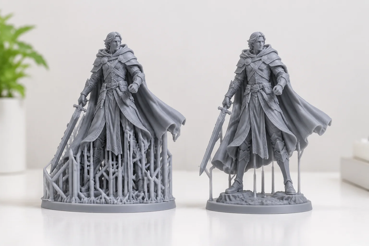
Modern stereolithography slicers furnish operators with three baseline automation presets: light, medium, and heavy. While software marketing often presents these presets as plug-and-play buttons for distinct build scales, our laboratory benchmarks reveal significant variations in how algorithmic solvers calculate point distribution across sharp compound curvatures. A standard preset applies uniform mathematical spacing rules across entire mesh hulls without distinguishing between functional mating flanges and non-critical bottom draft faces.
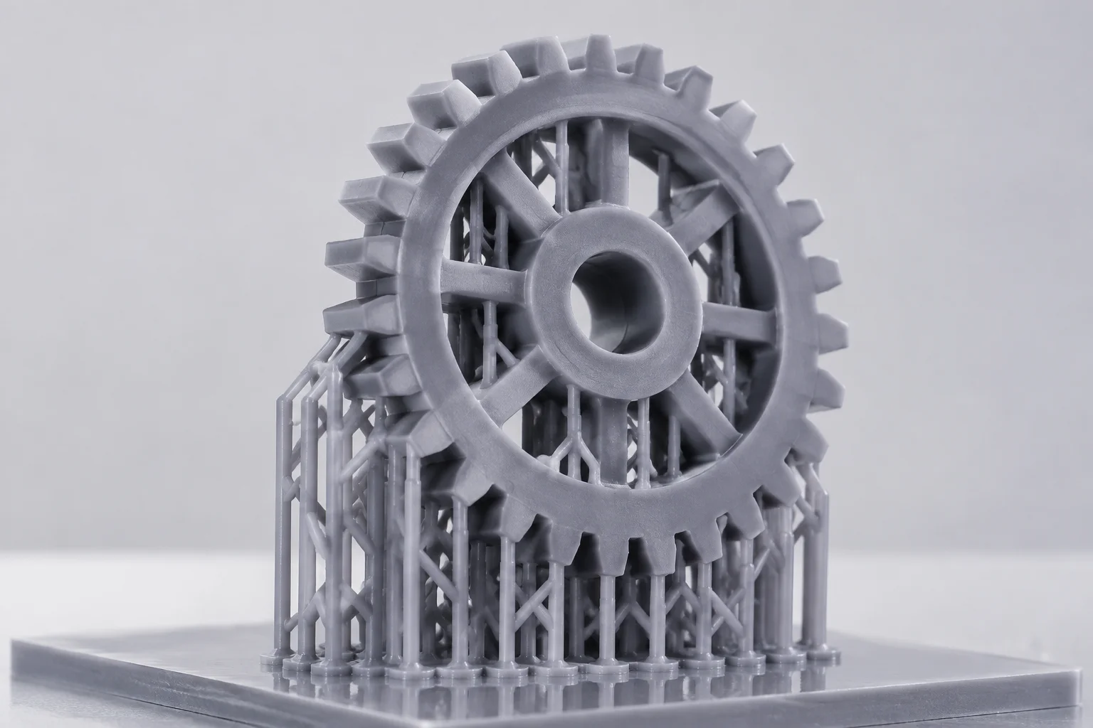
When an engineer selects a heavy preset, the algorithm scales both the touchpoint penetration depth and trunk column diameter simultaneously. The heavy preset elevates contact diameter to approximately 0.65mm and reduces mutual lattice spacing to under 2.2mm. On bulky engineering brackets, this brute-force approach ensures platform retention against severe separation forces, yet it introduces massive post-curing divots that can exceed 180 microns in localized depth after mechanical snipping.
02
Benchmark Overhang Testing
To evaluate default algorithm fidelity, our team ran comparative print runs using standardized test artifacts featuring steep cantilevers, stepped filleted domes, and hollow vertical cylinders. Three key failure modes systematically emerged when trusting factory presets without targeted intervention:
- Light presets frequently drop critical initial local minima on sudden cross-sectional transitions, yielding delaminated resin sheets across steep horizontal cantilevers.
- Medium configurations cluster contact tips indiscriminately around narrow concave grooves, creating solid resin bridges that resist manual cutter access and require extensive filing.
- Heavy defaults apply oversized anchor contacts to fragile trailing edges, prompting edge tear-out during post-print wash agitation and green-state part de-bridging.
03
Hybrid Overrides & Workflows
Production reliability does not mandate discarding automation entirely. Instead, experienced technicians implement a tiered hybrid workflow. The optimal technique initiates auto-generation under a conservative medium preset to anchor the principal cross-sectional mass against release forces, followed immediately by manual point culling along aesthetic or functional surface regions.
Operators can convert individual contact tips on critical chamfers to ultralight 0.30mm diameters while retaining heavier 0.60mm anchor columns along unseen bottom base lines. This two-phase pipeline cuts layout setup duration down to under two minutes per build plate while completely sidestepping the severe geometric distortion common to pure default automation.
Diagnostic Modeling
Evaluate Your Model Risk Profile
Calculate peel forces and assess pitting probability prior to sending your next job to the build platform.
Launch Risk Matrix