Balancing material flow dynamics, vat replenishment rates, and cross-sectional peel tension across high-viscosity photopolymers.
Bobbie DraperAugust 25, 20268 Min Read
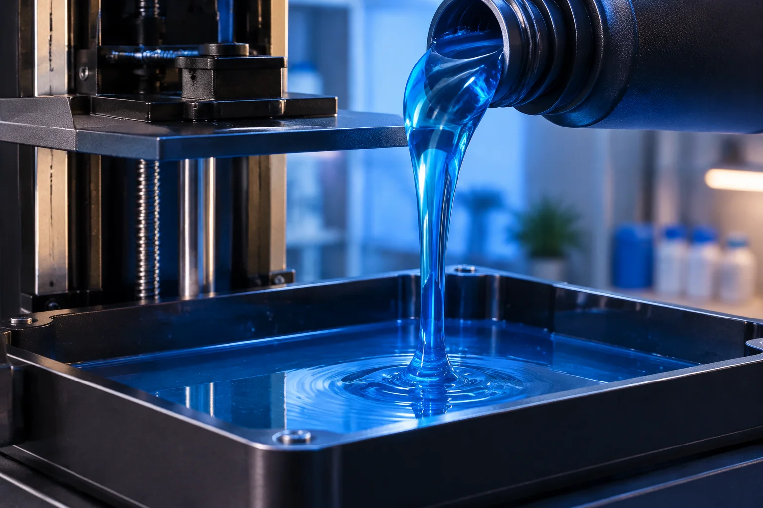
High-viscosity photopolymer undergoing controlled dispense into a heated resin tank.
01
Hydraulic Drag and Vat Replenishment
Photopolymer resins span a substantial rheological spectrum, ranging from standard prototyping polymers measuring roughly 300 to 500 mPa·s up to heavily filled composite ceramic or polyurethane resins exceeding 4000 mPa·s at ambient room temperature. When a build platform lowers into the vat after the peel step, the fresh liquid must rapidly flow across the tank base to refill the void beneath the cured cross-section. Viscous formulations resist this inward rush, creating localized fluid displacement deficits and severe hydrodynamic shear forces that directly impinge against slender support struts.
As cross-sectional area expands, hydrodynamic resistance escalates non-linearly. The resin cannot evacuate smoothly from under descending parts, generating positive hydraulic squeeze pressures against newly exposed contact nodes. Conversely, when the elevator pulls away during separation, thick resins demand protracted settling periods to avert fluid cavities. Ignoring these fluid mechanics routinely causes support deflection, microscopic layer shifts, and delamination at critical strut contact interfaces.
Thick photopolymers behave as viscous dampers inside the tank, exerting continuous lateral hydrodynamic pressure across every support column during vertical stage repositioning.
— SupportFootprint Materials Laboratory
02
Flow Resistance and Strut Spacing Rules
Slicing software algorithms typically calculate support density solely by evaluating overhang angles and downward volume vectors, entirely ignoring the physical viscosity of the liquid surrounding the network. When dense clusters of support columns stand within millimeters of each other, they form a porous fence that impedes resin replenishment. The following baseline design rules establish appropriate liquid pathways through dense support forests:
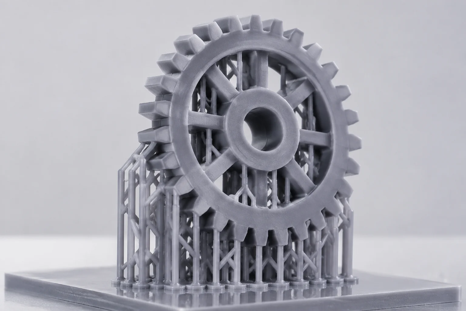
Expand inter-column lateral spacing by roughly twenty-five percent when printing resins exceeding 1200 mPa·s to eliminate viscous stagnation zones.
Enlarge primary strut shaft diameters from standard 0.8 mm to 1.2 mm while keeping contact tips sharp, resisting sideways fluid deflection.
Construct triangular cross-directional truss bracing to stiffen support arrays against lateral hydraulic wash during build plate immersion.
03
Calibration Protocols for High-Viscosity Resins
Achieving dimensional stability across high-viscosity formulations requires balancing support pillar quantity against individual strut stiffness. Rather than crowding a fragile overhang with thirty micro-supports that choke flow, operators obtain superior results by placing fewer, stouter columns reinforced with diagonal ties. This open architecture preserves fluid channels beneath the model, accelerating vat self-leveling and eliminating resin starvation pockets that trigger partial layer voids.
Elevating vat temperatures between 32°C and 35°C cuts resin viscosity significantly, frequently by more than half compared to room temperature. Pair this thermal regulation with a prolonged light-off delay or lift wait timer. Allowing two to four seconds for the viscous boundary layer to settle before initiating UV exposure guarantees that cured layers adhere to motionless liquid, preserving geometric fidelity across intricate dental arches, miniature castings, and industrial housings.
04
Frequently Answered Questions
As the build platform plunges downward into the vat, thick photopolymer cannot displace quickly enough, forming a heavy horizontal fluid wave. This hydraulic wave pushes against slender support columns, bending them out of alignment or ripping fine contact tips directly off the green part.
Dense clusters of supports choke resin flow. The proven strategy reduces overall support density while beefing up individual shaft diameters and interconnecting cross-trusses, giving the dense resin open corridors to flood back across the vat floor.
Extend the exposure wait delay by two to four seconds and decelerate platform lowering speeds. This waiting interval allows viscous fluids to reach complete rest and equilibrium before the UV light source initiates the next layer exposure.
Keywords:Resin RheologyHydraulic PeelSupport Density
Engineering Diagnostic Tools
Calculate Resin Volume and Peel Risk
Evaluate material consumption, peeling tension, and support lattice stability with our specialized analytical calculators.