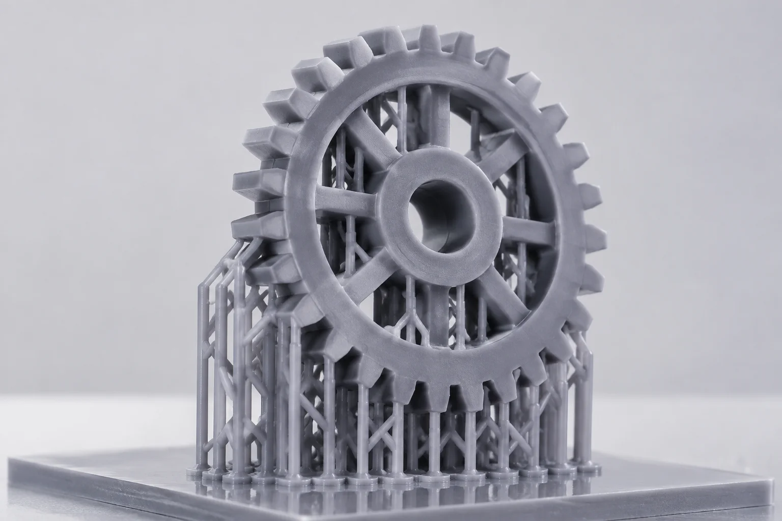
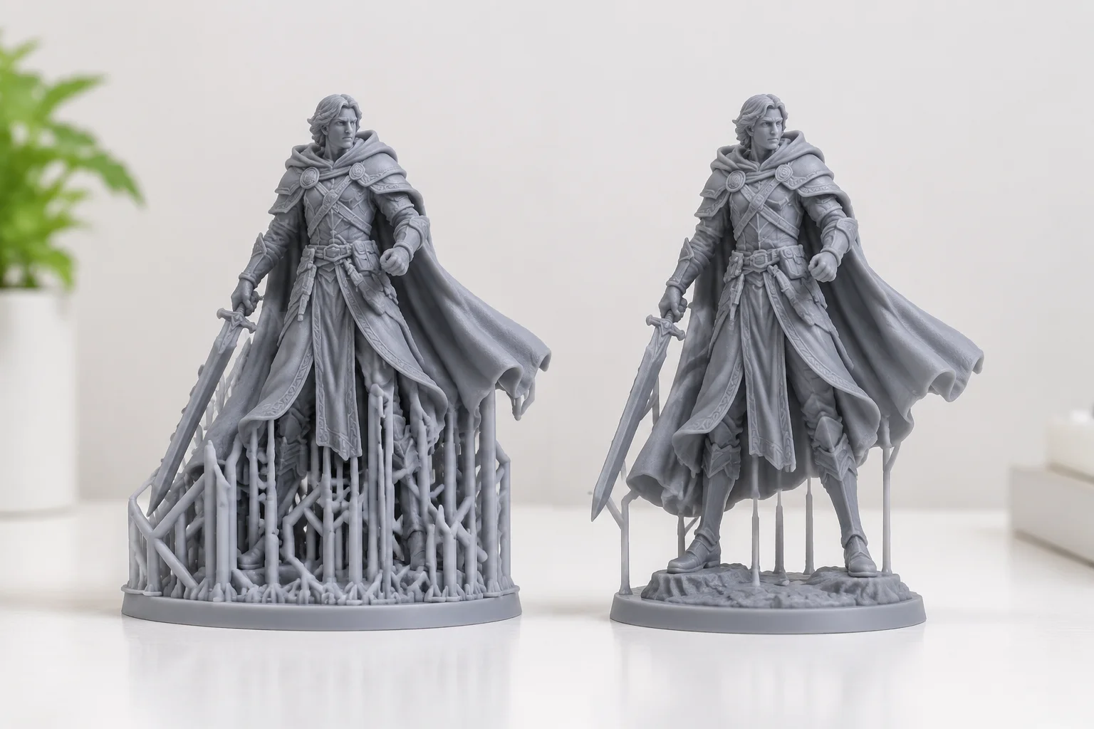
Overriding automated algorithms: strategic truss placement, local island stabilization, and touchpoint conservation for complex geometries.
Filip InarosAugust 20, 20269 Min Read
Manual editing environment: inspecting layer slices and placing touchpoints along primary downward overhangs.
01
When Automated Generation Algorithms Fail
Automated support generators rely on geometric ray-tracing and uniform overhang angles to deposit pillars across inverted surfaces. While software algorithms process standard geometries reliably, they systematically miscalculate peel tension vectors on thin walls and asymmetrical volumes. Auto-placement algorithms treat every polygon uniformly, often peppering pristine cosmetic facets with redundant contact nodes while neglecting subtle local minima that cause early delamination.
In resin stereolithography, peeling forces fluctuate dynamically as the cross-sectional cured area expands and contracts throughout the build cycle. Relying solely on default auto-generation presets results in either catastrophic structural collapse from unanchored islands or severe surface degradation from dense support forests. Manual placement bridges this gap by aligning support stiffness directly with peeling dynamics rather than static angle thresholds.
The Strategic Hierarchy: Anchors, Ribs, and Stabilizers
Constructing a dependable manual support network requires a tiered structural hierarchy. Rather than deploying identical pillar diameters across the entire model, distribute load resistance according to print chronology:
Heavy primary anchors at the initial low point (island origin) to absorb initial peel shocks and secure subsequent layers to the build platform.
Tapered secondary supports spaced strategically along perimeter contours to prevent lateral deflection and curling during layer separation.
Micro-contact stabilization pins along cosmetic or mating margins to preserve fine dimensional tolerances without leaving deep pitting scars.
03
Preserving Critical Facets and Mating Boundaries
Functional assemblies and aesthetic parts frequently present sealing lips, fastener recesses, and high-visibility contours that must remain pristine. When automatic support routines generate pillars on these surfaces, manual post-processing and sanding inevitably compromise part tolerances. Relocating contact points to sacrificial draft angles or concealed undercuts protects these crucial geometries from scarring.
By angling support trusses outward from non-critical surfaces and utilizing cross-bracing lattices, you can brace steep overhangs without contacting the functional edge directly. This structural bridge technique transfers peeling tension away from delicate boundaries while preventing local flex that causes layer stepping.
04
Support Strategy Troubleshooting & FAQ
Scrub layer-by-layer through the slicer layer slider from bottom to top. Watch for any independent pixels or floating cross-sections appearing in red before connecting to the body. Every newly appearing local minimum requires an immediate manual anchor placed at its exact lowest point.
For standard rigid or tough resins, initial structural anchors should measure between 0.65 mm and 0.85 mm at the contact point. Secondary stabilizers along perimeter walls should range between 0.35 mm and 0.45 mm to ensure clean breakaway without surface divots.
High-aspect-ratio pillars flex under hydraulic resin resistance during plate retraction. To prevent buckling, interconnect adjacent supports using horizontal truss crossbars spaced every 8 to 12 mm, or group them into triangular cluster bases.
Keywords:Manual SupportsSLA OptimizationPeel Force Management
Risk Evaluation Tool
Assess Your Part Scarring & Peel Risk
Evaluate your model geometry against surface defect probabilities and peeling force thresholds before curing.