Suction Cupping Mechanics and Mechanical Separation
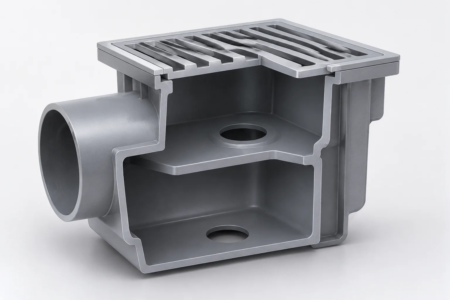
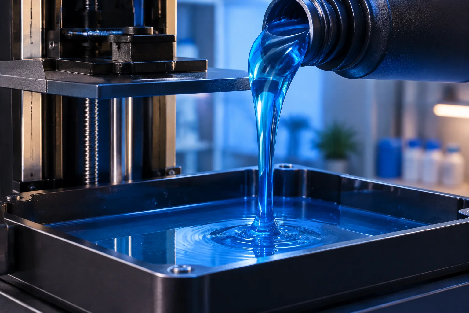
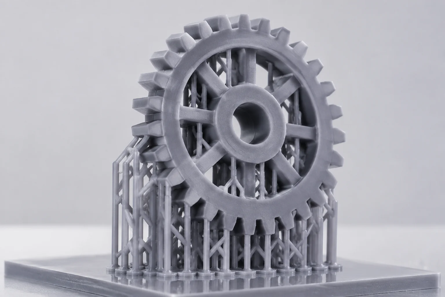
In inverted stereolithography systems, closing a hollow volume facing the vat film creates a potent suction cup during the upward peel motion. As the print stage elevates, uncured liquid resin inside the enclosed hollow cannot escape freely, establishing a strong localized negative pressure against the flexible release film. This concentrated suction force regularly exceeds the green strength of freshly cross-linked resin layers, leading directly to wall ruptures, layer delamination, or severe dimensional distortion across horizontal planes.
Failure modes manifest distinctively depending on resin viscosity and peel velocity. Low-viscosity formulations tend to peel with micro-tears along perimeter edges, while high-viscosity functional polymers induce total hydraulic collapse or massive blowouts that spill uncured liquid directly into adjacent support lattices. Placing dedicated vent apertures breaks this vacuum differential instantly, allowing fluid displacement to stabilize across every layer transition without tearing delicate structural features.
A hollow cavity without an active air vent functions as a hydraulic piston during every peel step. Venting early near the build interface neutralizes internal suction before mechanical tear forces accumulate.
— Fred Johnson, Additive Process Engineer
02
Shell Thickness Calculations and Internal Stabilization
Choosing an appropriate shell wall thickness balances resin conservation against component rigidity during processing. Thin shells under 1.5 millimeters deflect easily under peeling forces, inducing visible layer banding and perimeter warping. Conversely, excessive wall thicknesses beyond 3.5 millimeters diminish material savings and trap high thermal energy during secondary ultraviolet exposure. Practical benchmarks demonstrate consistent reliability when implementing balanced geometric bounds:
Maintain standard perimeter wall thickness between 2.0 mm and 2.5 mm for medium-scale enclosures and structural housings.
Introduce internal chamfered ribs or perforated gussets across broad unsupported hollow spans exceeding 45 mm in length.
Avoid acute interior re-entrant corners inside hollow cavities to eliminate uncured resin pooling and stress concentrations.
03
Orifice Sizing, Dual Placement, and Solvent Evacuation
A common misconception in mesh preparation involves creating a single drainage hole at the lowest point of the hollow model. A single orifice cannot displace liquid efficiently because incoming air cannot enter simultaneously while viscous resin discharges. To achieve laminar air-liquid exchange, place at least two distinct orifices: a primary drainage hole located at the lowest layer closest to the build plate, and a secondary atmospheric vent located at the highest opposite elevation of the chamber.
Drain hole diameters should measure no less than 3.0 mm for standard photopolymers, expanding to 4.5 mm or 5.0 mm when deploying engineering formulas with heightened viscosity. During post-processing, dual holes allow isopropyl alcohol or tripropylene glycol monomethyl ether to flush through the interior freely under agitated washing, clearing residual liquid resin that would otherwise react exothermically or fracture the part during final chamber post-curing.
04
Frequently Addressed Engineering Questions
Uncured photopolymer resin trapped inside an unvented cavity continues to undergo slow chemical polymerization while emitting volatile components. This process produces internal gas pressure and moisture uptake, while the exterior shell shrinks during secondary curing. The resulting differential tension inevitably splits the outer walls along natural layer boundaries.
Yes. Most slicing tools generate matched cylindrical plugs extracted directly from the hole cutouts. After thoroughly washing and curing the interior cavity, insert the plug using a small drop of matching liquid resin, then cure the joint locally with an ultraviolet pen before sanding smooth.
Place the initial aperture within 1.0 mm to 2.0 mm of the lowest slice defining the cavity boundary. Placing the hole higher leaves a blind pocket where uncured resin remains trapped during the earliest layers, creating suction cupping until the toolpath reaches the hole perimeter.
Keywords:HollowingDrain HolesSuction Cupping
Quantitative Tools
Assess Peel Tension and Cavity Risk Factors
Evaluate cross-sectional areas, shell thickness safety margins, and drainage requirements using our engineering risk matrices.