Partitioning oversized or intricate geometries into printable sub-assemblies while maintaining seam registration, surface finish integrity, and predictable support placements.
Josephus MillerOctober 2, 20268 Min Read
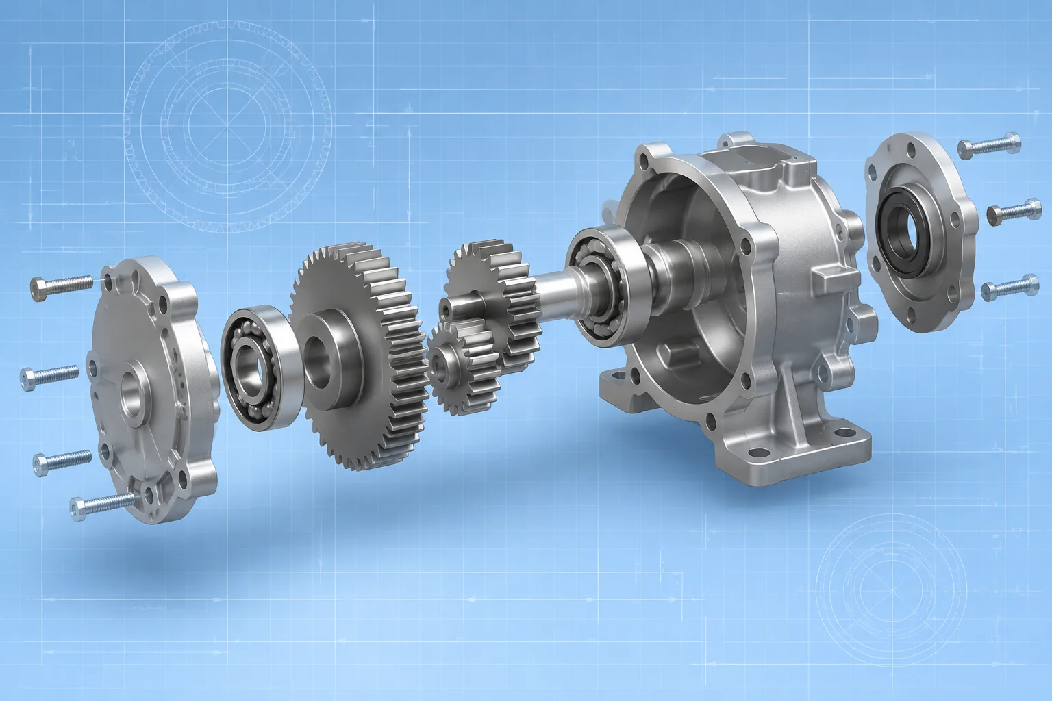
Digital mesh decomposition displaying split boundary interfaces and interlocking registration dowels.
01
Sectioning Geometry Along Natural Contours
Monolithic parts frequently challenge printer build envelopes or introduce severe orientation compromises where peel tension bends slender cantilevered facets. Splitting an assembly into multiple solid bodies resolves spatial bottlenecks, yet introducing arbitrary cut planes brings immediate structural and aesthetic challenges. The primary objective involves positioning cut boundaries along organic contours, shadow recesses, or geometric steps where seam lines remain visually discreet after post-curing.
Flat perpendicular cuts across expansive visible faces require intensive manual smoothing and risk visible mismatch from minor cure variations. Slicing with interlocking step joints or undulating profile cuts expands contact bonding area for structural adhesives. At the same time, this methodology shifts support contact anchors away from cosmetic outer faces by confining touchpoints exclusively to concealed internal mating channels.
Splitting a model is not merely a build volume workaround; it is an orientation strategy to isolate critical cosmetic facets from peeling shears and support contact pits.
— Josephus Miller, Additive Tooling Engineer
02
Designing Self-Aligning Mating Geometry
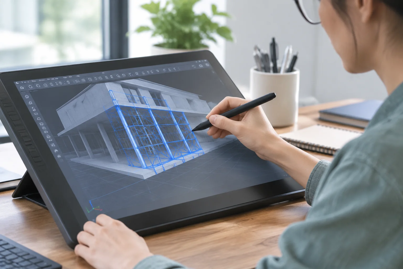
Relying on manual clamping during post-cure assembly often causes angular misalignment and stepped seam borders. Sub-assemblies require positive registration features modeled directly into CAD master files before mesh export into PreForm.
Chamfered indexing keys: Implement asymmetric pins, sliding dovetails, or hexagonal keys with a 0.5 mm lead-in chamfer to facilitate instant alignment under viscous resin conditions.
Offset boundary clearances: Maintain a uniform diametrical clearance of 0.15 mm to 0.20 mm between male and female facets to prevent hydrostatic resin entrapment during insertion.
Internal adhesive relief channels: Model microscopic 0.3 mm deep channels inside the joint pocket that allow cyanoacrylate or two-part epoxy to distribute without overflowing along external seams.
03
PreForm Grouping, Nesting, and Thermal Uniformity
Once imported into PreForm as separate solid bodies, orientation must prioritize each sub-part's specific mechanical axis. Individual bodies should tilt between 30 and 45 degrees relative to the peel direction, ensuring peeling forces act progressively across narrow cross-sections rather than sudden large surface areas. Orienting mating interfaces away from the build platform confines support contact scars strictly to non-critical internal zones.
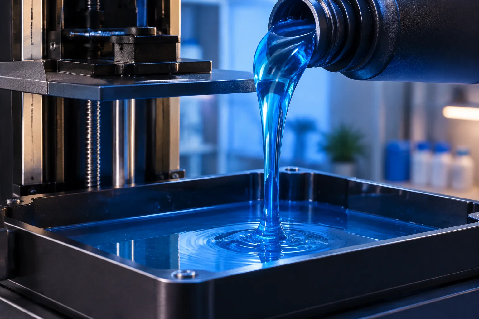
Packing multiple sub-assemblies into a single build job introduces thermal and flow gradients across the resin tank. Distribute mass evenly across the mixer stroke path rather than clustering dense components in the center. Grouping parts with identical layer height parameters preserves synchronized curing speeds and prevents geometric discrepancies that could disrupt boundary alignment when assembled.
04
Practical Considerations & FAQ
For standard and engineering photopolymers, a radial clearance of 0.08 mm to 0.10 mm (0.16 mm to 0.20 mm total diametrical offset) provides smooth dry-fitting while compensating for optical light bleed and post-cure shrinkage without binding.
Separate post-curing promotes uniform UV exposure across all surfaces and prevents trapped liquid resin inside tight joints. For precision interference fits, dry-assemble components with temporary jigging before final post-cure to lock alignment.
When bonded with structural methyl methacrylate (MMA) or polyurethane adhesives into properly keyed geometry, the bonded interface matches or exceeds the tensile yield strength of uncured resin bulk material.