Techniques for reducing post-processing marks, micro-divots, and separation craters on convex and organic geometries.
Alex KamalSeptember 12, 20266 min read
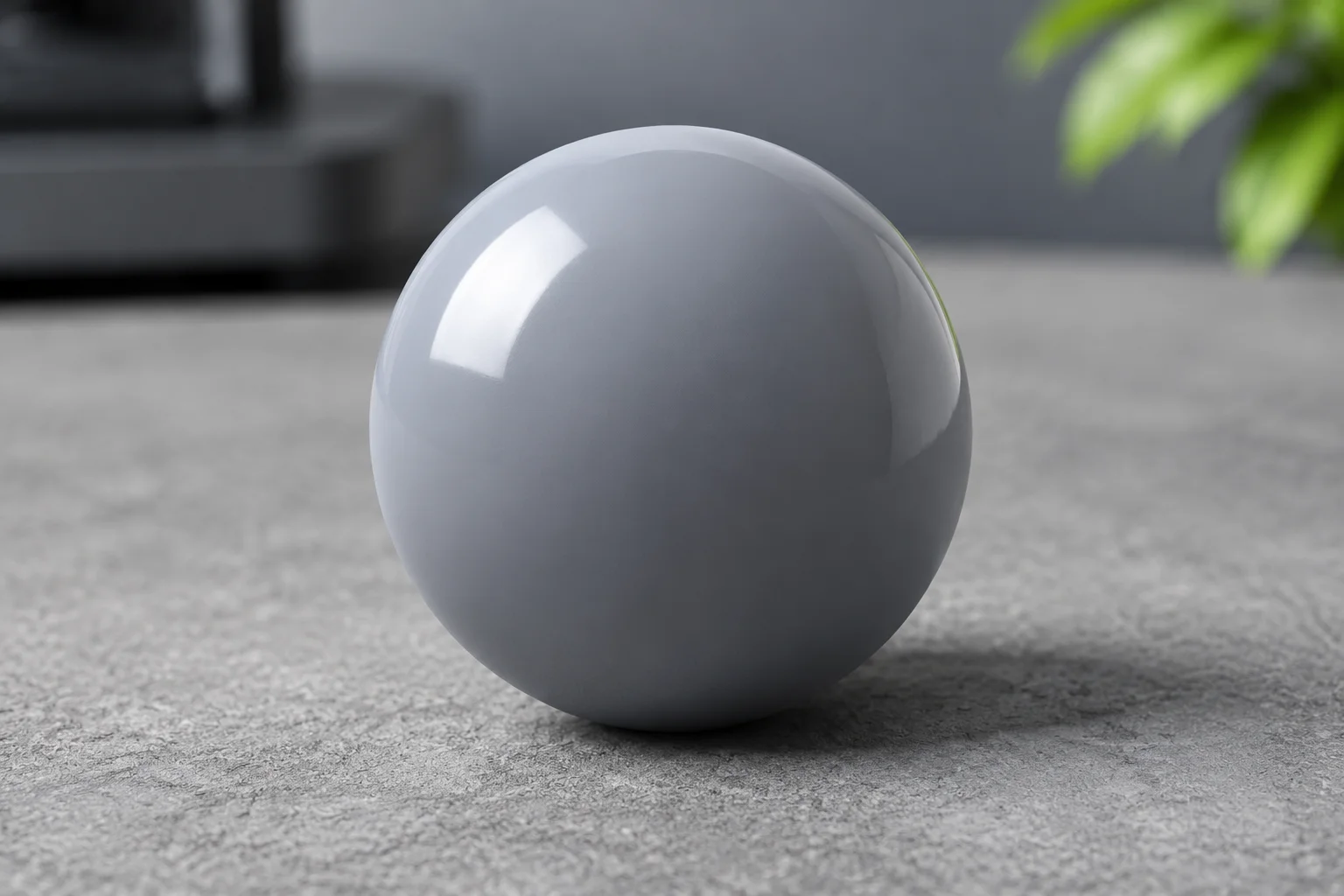
Flawless specular continuity across a curved resin model with optimized touchpoints
01
The Mechanics of Subsurface Fracture on Convex Surfaces
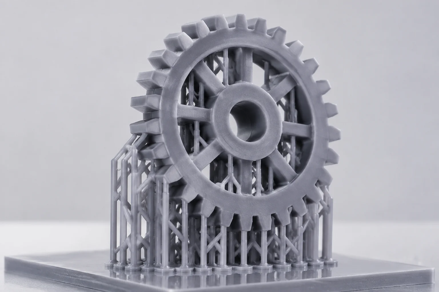
Curved and spherical surfaces in SLA additive manufacturing are uniquely prone to pitting when support tips are detached. During traditional post-processing, pulling or tearing a support pillar creates a high force concentration at the junction where the cured resin penetrates the exterior shell. Because cross-linked photopolymers are inherently brittle, the fracture plane often propagates beneath the nominal surface perimeter, carving out a microscopic crater rather than separating flush.
These pits create significant aesthetic and functional challenges because light reflections over smooth convex faces instantly highlight even sub-millimeter depressions. While flat faces can often be leveled rapidly on a sanding block, re-establishing a continuous spherical radius requires delicate micro-filling with liquid resin or aggressive progressive sanding that risks distorting the part's dimensional accuracy. Addressing this defect therefore requires tackling peel force distribution and slicer contact geometry before the print begins.
Snapping cured supports off curved geometries inevitably tears into the part core. True surface continuity demands trimming while the resin remains ductile in its green state.
— Alex Kamal, Senior Additive Manufacturing Specialist
02
Optimizing Touchpoint Geometry and Penetration Depth
Preventing subsurface tearing begins inside the slicing environment by modifying touchpoint parameters. Default software presets often default to aggressive penetration depths of 0.35 mm to 0.50 mm to prevent print detachment. However, convex curvatures naturally shed shear loads across multiple coordinates, allowing operators to safely reduce penetration without inviting print failure.
Constrain touchpoint contact diameter between 0.30 mm and 0.40 mm on visible aesthetic contours, relying on secondary structural trusses lower down the geometry.
Reduce penetration depth to 0.12 mm to 0.18 mm, ensuring the ultimate mechanical cleavage plane remains flush with the theoretical surface wall.
Implement spherical or tear-shaped contact tip geometry rather than sharp cylinders to diffuse dynamic separation forces more evenly across adjacent layer lines.
03
Thermal Conditioning and Green-State Trimming Protocols
The single most effective operational practice for eliminating cratering is excising supports while the part is still in its green state prior to secondary UV post-curing. Uncured resin matrices maintain a degree of plastic ductility, meaning that razor cuts or micro-shear clipper actions sever the joint cleanly through local plastic deformation rather than glass-like brittle fracture.
Submerging the washed green part in a clean water bath warmed to 45°C to 50°C for approximately two minutes further softens the support joints. Technicians can then either cut stalks with precision flush cutters 0.5 mm above the surface or gently peel the pliable truss away without tugging. The minute remaining positive nub is far simpler and faster to level flat with 1000-grit micro-abrasive paper than repairing a hollow divot.
04
Frequently Addressed Questions
When fully cured resin supports are ripped off manually, tensile force forces the fracture line along the path of deepest penetration inside the part matrix. The material snaps below the skin line, dislodging a microscopic pit.
Water temperatures between 45°C and 50°C soften thin support stalks quickly without reaching the heat deflection temperature of bulk walls. Keep the immersion brief (under 120 seconds) and allow the component to cool before applying handling pressure.
Use wet silicon carbide abrasive sheets starting at 800 grit to gently knock down positive remnants, followed by 1200 and 2000 grit with light circular movements to refine the specular reflection across the curve.
Keywords:Surface QualityTouchpoint TuningGreen State Excision
Engineering Risk Calculator
Assess Curvature Scarring Probability
Calculate defect risk based on your model radius, resin durometer, and contact diameter with our interactive risk matrices.