 Tough Resin
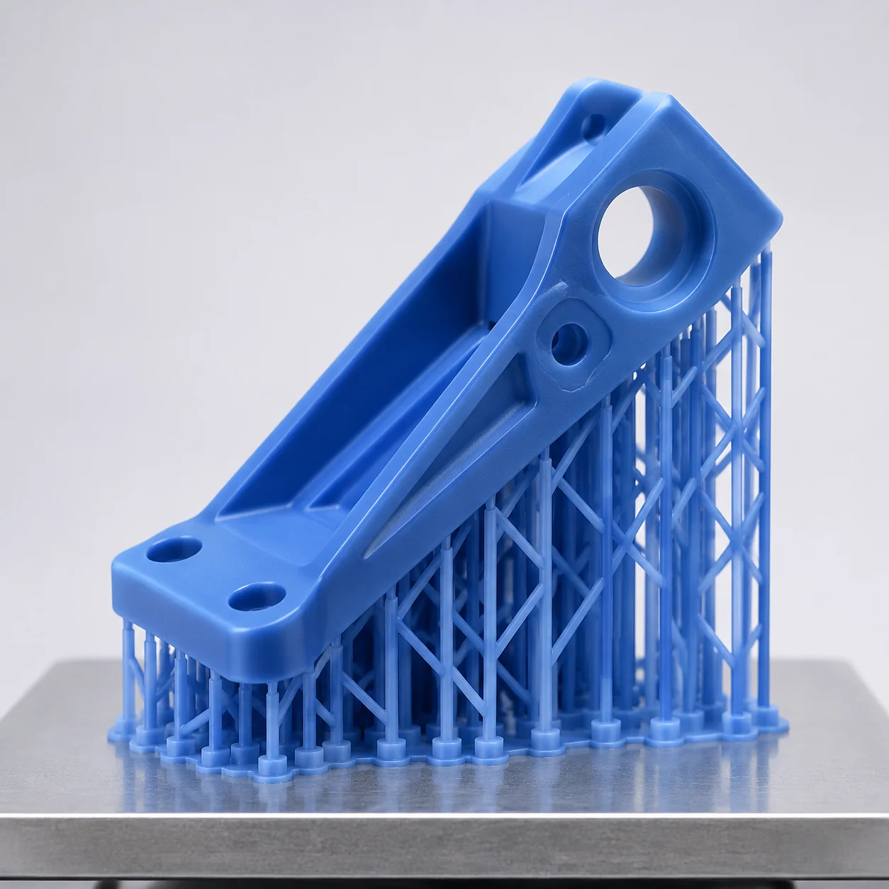
Mechanical Bracket Forty Five Degree Tilt
Balancing cantilever deflection forces and peel tension using a 45-degree angle lattice.
Medium Complexity
View Setup
Internal cavities and fluidic circuits demand a non-zero downward trajectory at every layer boundary. Tilting manifolds between 35° and 52° maintains natural gravity drainage, preventing uncured resin polymerization inside functional conduits.
Boundary configurations, material attributes, and mechanical orientation angles verified during print setup validation.
Internal conduits present a distinct mechanical challenge in stereolithography. When printing complex manifolds flat against the build plate, horizontal channel ceilings trap viscous liquid polymer in enclosed pockets. The subsequent peel motion creates extreme hydraulic suction cups, tearing delicate channel dividers or causing complete wall blowouts.
Orienting the manifold block at a continuous dual-axis angle establishes an uninterrupted negative slope from the deepest junction straight to the lowest exit port. Clear resin particularly benefits from this pathway because stray light scattering through transparent walls otherwise cures the stagnant resin film, permanently restricting microfluidic passages.
Visual representation of internal channel inclination, gravity exit vectors, and clear substrate penetration angles.
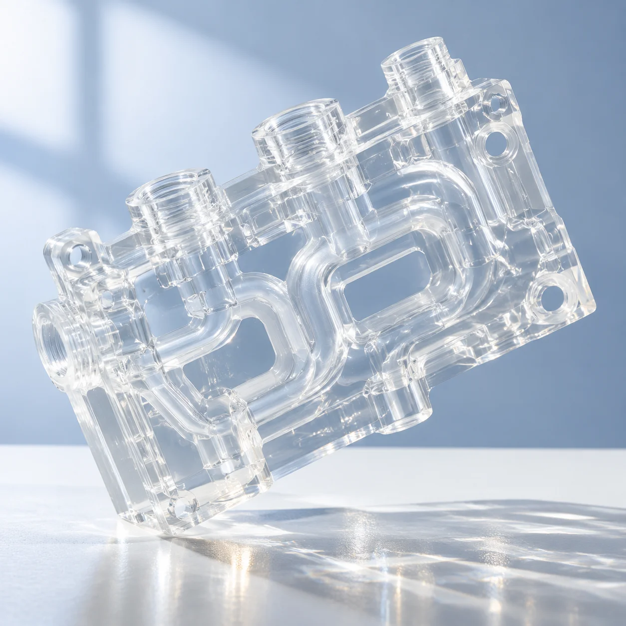
The backlit clear manifold specimen showcases unobstructed internal lumens without secondary support structures. By rotating the part so all hydraulic passages empty downward into the vat during platform ascension, excess uncured polymer flows back into the tank via natural gravity, leaving a thin, uniform resin boundary layer that rinses out thoroughly during solvent agitation.
Quantitative metrics evaluating resin egress velocity, suction force reduction, and lumen dimensional precision.
Executing accurate fluidic channels requires strict alignment between the CAD model's interior centerline curves and the printer build axis. Slicers must be verified layer-by-layer to catch trapped air bubbles or resin dams before starting the print sequence.
Practical answers regarding resin viscosity, lumen sizing, and post-wash clearing methods.
Connect with our technical desk to analyze CAD channel geometry or evaluate auto-drain configurations.
Submit your component specifications to review layer cross-sections, resin flow pathways, and orientation tilts before running production cycles.
Examine adjacent orientation studies focusing on delicate geometries, cavities, and structural load alignment.
Tough Resin
Balancing cantilever deflection forces and peel tension using a 45-degree angle lattice.
 Clear Resin
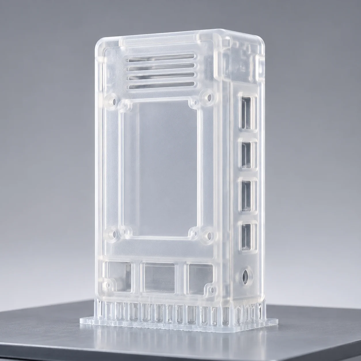
Orienting hollow enclosures vertically with perimeter venting to eliminate suction cups.
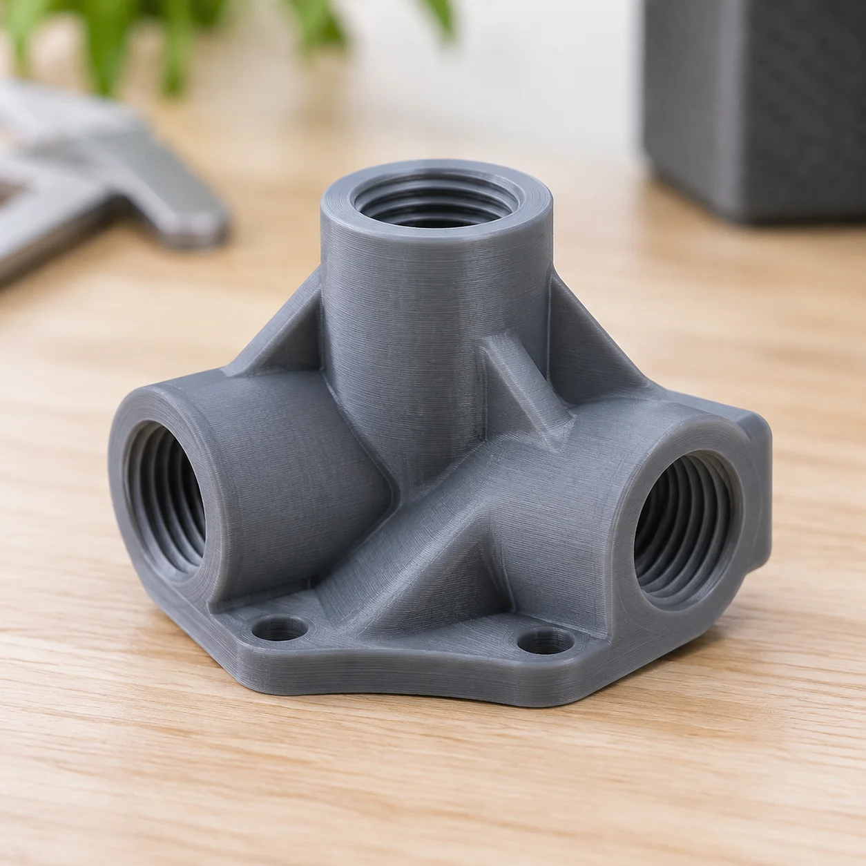 Tough Resin
Vertical axis alignment ensuring clean internal thread pitch without interior support scars.