
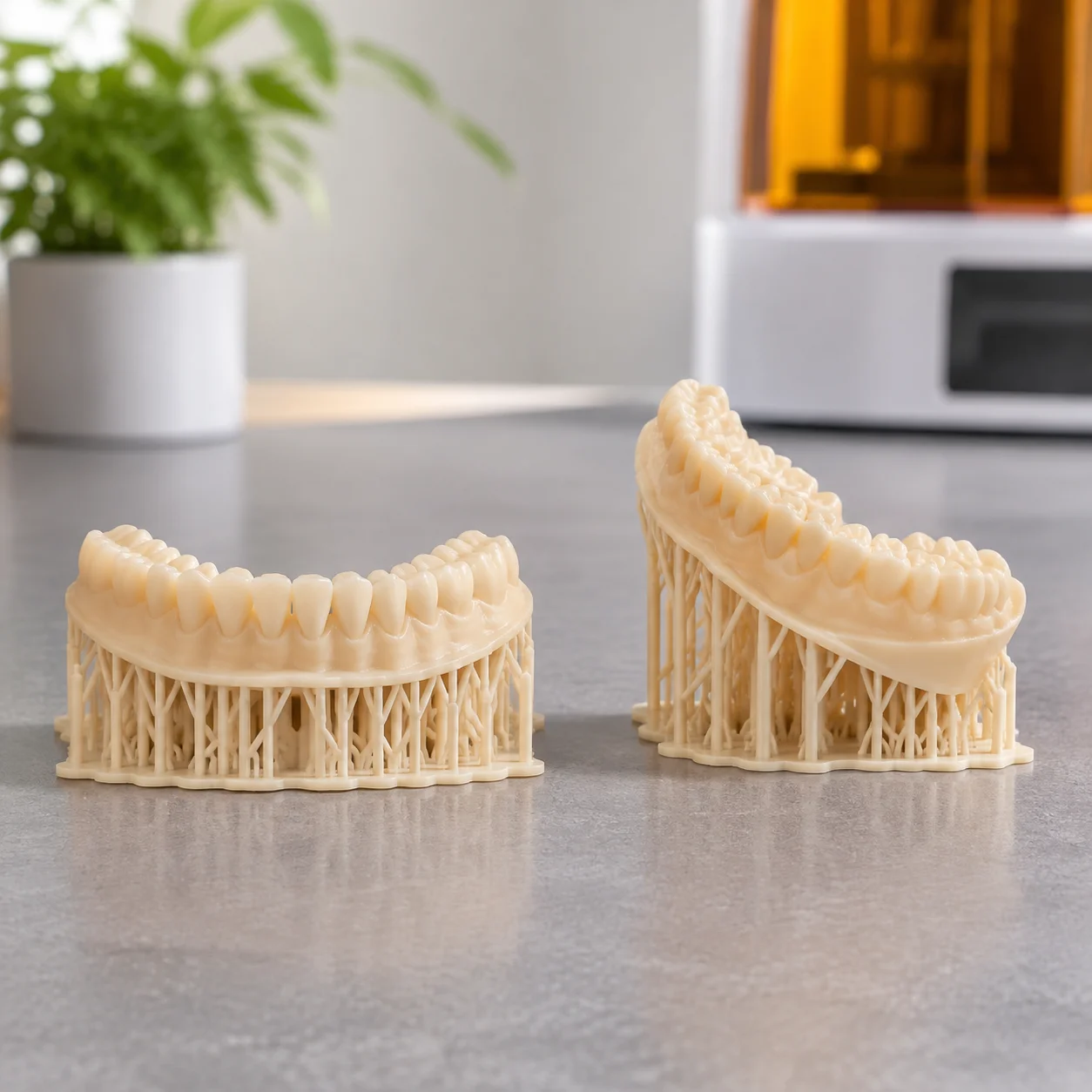
 Model Resin
Dental Arch Flat versus Angled
Comparative evaluation of support placement on critical anatomical margins versus heel-elevated setups.
Setup Protocol
View Setup
Methodological orientation guide for internal metric and imperial threads in tough resins to eliminate bore supports while preserving lead pitch fidelity.
Critical positioning angles and core slicing boundaries required for reliable thread resolution.
Threaded cavities present a common challenge in stereolithography. When internal threads tilt at shallow angles relative to the build plate, slicers generate support touchpoints directly across the thread ridges. Removing these supports shears tooth crests and ruins mating clearances. Aligning the central axis of the bore perpendicular to the build platform allows each thread pitch to self-support during photopolymerization.
Tough resin formulations exhibit balanced elongation and impact resistance, making them ideal for functional fasteners. However, uncured liquid resin easily pools in narrow thread roots due to surface tension and capillary action. Maintaining a steep vertical alignment ensures liquid resin drains freely between layer exposures, preventing thread clogging and maintaining precise tolerance bounds.
Visual representation of vertical bore positioning and uncured resin drain dynamics.
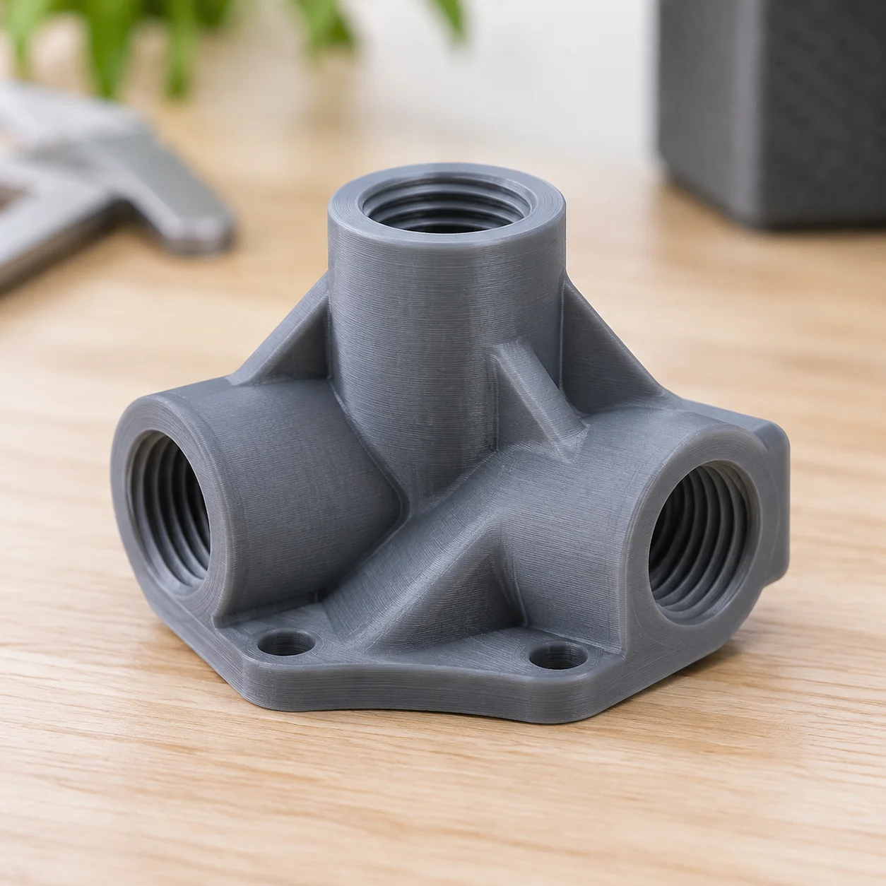
The diagram depicts a tough resin mechanical housing with an internal M6x1.0 thread oriented vertically along the Z-axis. By placing the bore entry pointing downward toward the resin tank, peel forces stay symmetric around the cylindrical perimeter. Each successive pitch forms an overhang angle well within the self-supporting threshold of 30° to 45°, leaving the thread crests and roots cleanly resolved without manual post-machining.
Key mechanical metrics and slicing tolerances observed in empirical test prints.
Consistent thread geometry depends on controlling local exposure bloom and suction peaks during separation cycles. Technicians inspecting finished parts should verify these three mechanical checkpoints:
Practical answers to common manufacturing hurdles when printing functional female threads.
Submit your part specifications for layout review and support-free thread positioning analysis.
Share your component dimensions to evaluate thread pitch feasibility, resin drainage channels, and fixture stability before production.
Explore alternative structural setups and support mitigation protocols across other mechanical geometries.
Model Resin
Comparative evaluation of support placement on critical anatomical margins versus heel-elevated setups.
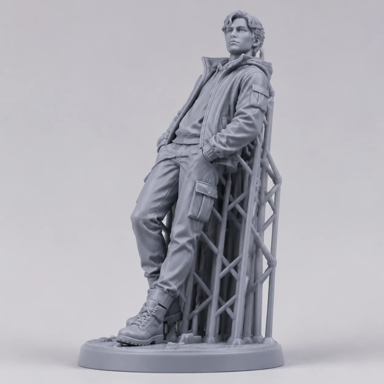 Standard Grey
Back-tilted posture directing support contact facets away from delicate facial features and organic textures.
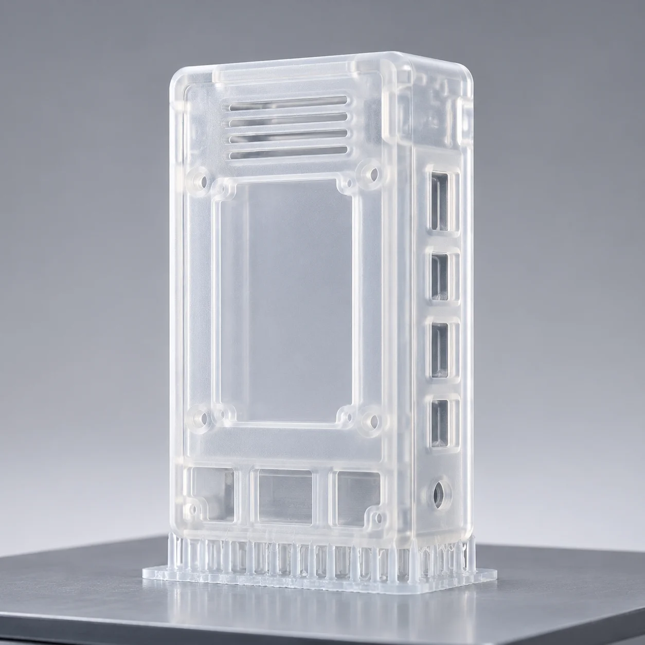 Clear Resin
Space-efficient vertical alignment designed to reduce surface peel drag and prevent thin wall warping.