Case Study • Technical Protocol #045

Mechanical Bracket Forty Five Degree Tilt

Minimizing cross-sectional layer area, managing peel force dynamics, and safeguarding critical mounting surfaces through tilted stereolithography positioning.

November 12, 2026 Structural Engineering 6 Min Read

Orientation & Geometry Analysis

Setting up functional mechanical components requires balancing peel force resistance, contact facet placements, and dimensional accuracy across load-bearing planes.

Resin Formulation: Tough Resin Primary Tilt Angle: 45° Off Z-Axis Structural Complexity: Medium Verification State: Empirically Tested

When orienting structural brackets on an inverted stereolithography platform, printing directly flat against the build plate creates an abrupt transition and massive cross-sectional peel suction. This sudden cross-sectional jump during early layer separation regularly introduces layer shifting or base separation. By rotating the bracket forty-five degrees relative to both horizontal axes, each cured layer forms a gradual diagonal profile, dispersing mechanical detachment forces evenly across the peeling cycle.

Tough Resin exhibits distinct viscoelastic elongation properties prior to complete UV curing. Cantilevering heavy bosses without an inclined angle risks plastic deformation under repeated vat peel cycles. An inclined posture of forty-five degrees establishes a self-supporting incline along gussets, concentrating point supports only on non-critical exterior facets while protecting high-tolerance fastener holes and planar mating faces from scarring.

Support Architecture & Contact Points

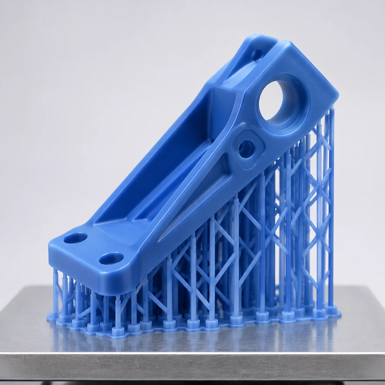
Visualizing anchor density, contact tip sizing, and facet clearance along the primary tensile axis.

Mechanical Bracket Forty Five Degree Tilt
45° Inclination • Tough Resin Truss

The structural bracket rests upon a tapered scaffold network with contact tip diameters graded from 0.50 mm along the base lead-in down to 0.35 mm along non-critical fillets. Critical fastener counterbores remain oriented upward away from the vat film, allowing unhindered resin runoff and preventing hydraulic entrapment. Notice how the internal ribbing guides peel force dissipation away from the central hinge junction.

Technical Specifications & Benchmarks

Quantified production benchmarks measured during iterative laboratory runs.

Peel Force Reduction -42% vs Flat Layout
Contact Touchpoint Count 38 Graded Struts
Post-Processing Time ~8.5 Minutes Fin Care
Dimensional Bore Tolerance ±0.06 mm Achieved

Key Setup Principles & Best Practices

To reproduce these geometric tolerances on standard SLA hardware, adhere strictly to boundary prep protocols. Never let planar faces run parallel to the vat release film, and ensure heavy mass concentrations are supported early in the print cycle.

  • Position critical bearing faces facing upward to eliminate pitting and manual grinding marks.
  • Maintain uniform 45-degree inclination along both pitch and roll vectors to prevent cupping vacuums.
  • Calibrate touchpoint penetration depth to 0.25 mm to allow clean, flush cutter separation without divots.

Frequent Technical Inquiries

Answers to common questions regarding forty-five degree bracket positioning and resin behavior.

Consult on Part Prep

Connect with our engineering editorial team to evaluate model slicing strategies, support placement files, or custom resin setups.

Review Your Orientation Strategy

Submit your design parameters for peer review on support touchpoint minimization, surface integrity preservation, and resin peel risk assessment.

Related Orientation Studies

Explore comparative analyses covering diverse structural geometries, medical devices, and thin-wall applications.

Dental Arch Flat versus Angled Healthcare

Dental Arch Flat versus Angled

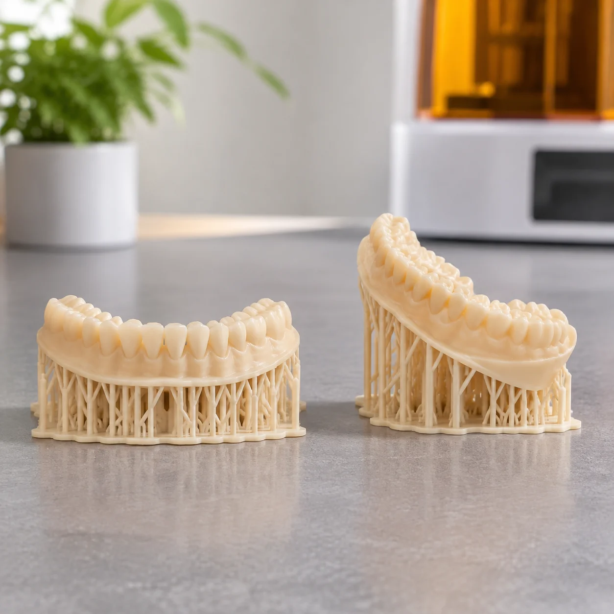
Comparative inspection of heel-supported 30-degree tilt versus flat plate orientation to safeguard occlusal surfaces.

Model Resin • High
View Setup
Miniature Figure Face Up Collectibles

Miniature Figure Face Up

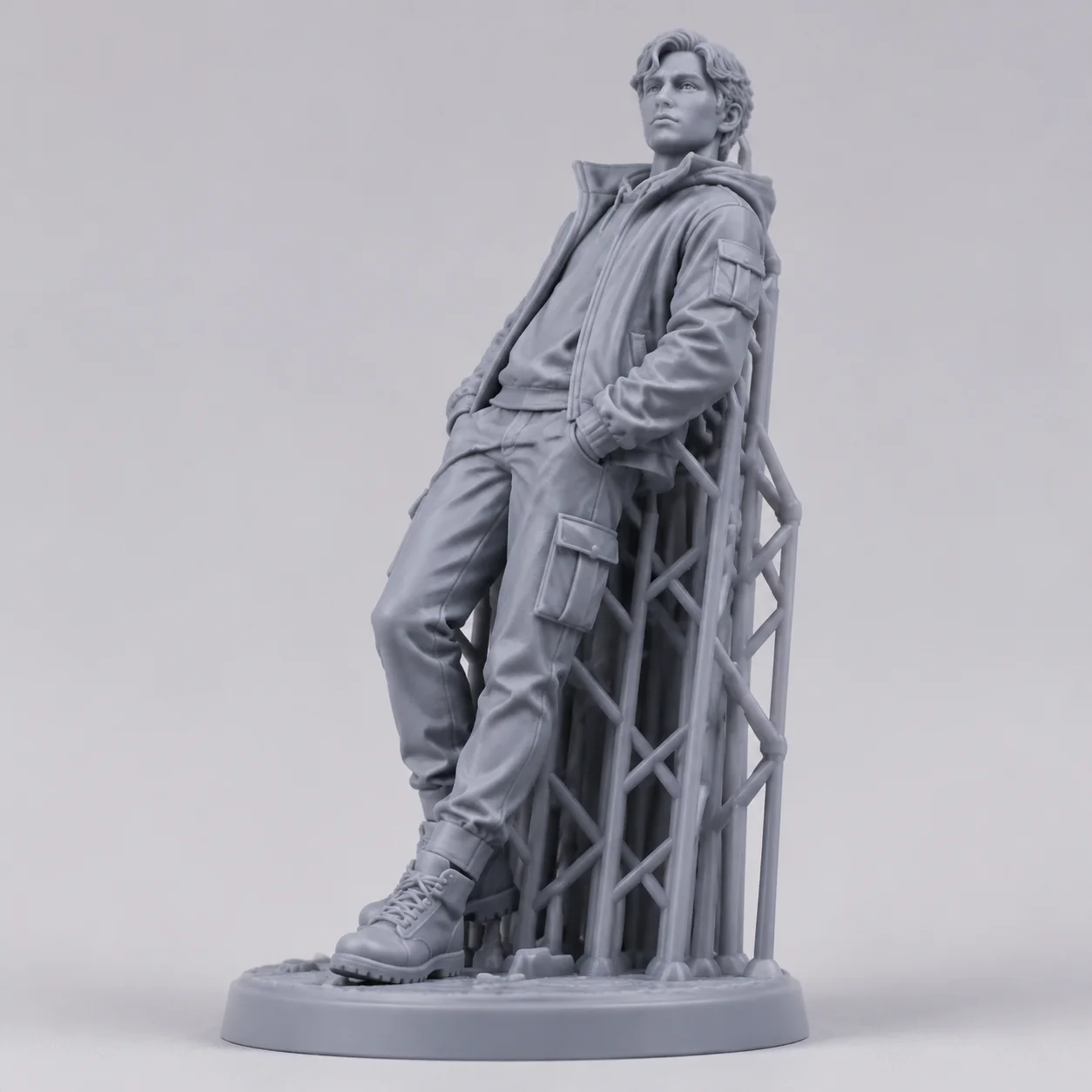
Backward tilt strategy ensuring delicate facial micro-features and drapery avoid contact scarring.

Standard Grey • High
View Setup
Enclosure Box Vertical Orientation Electronics

Enclosure Box Vertical Orientation

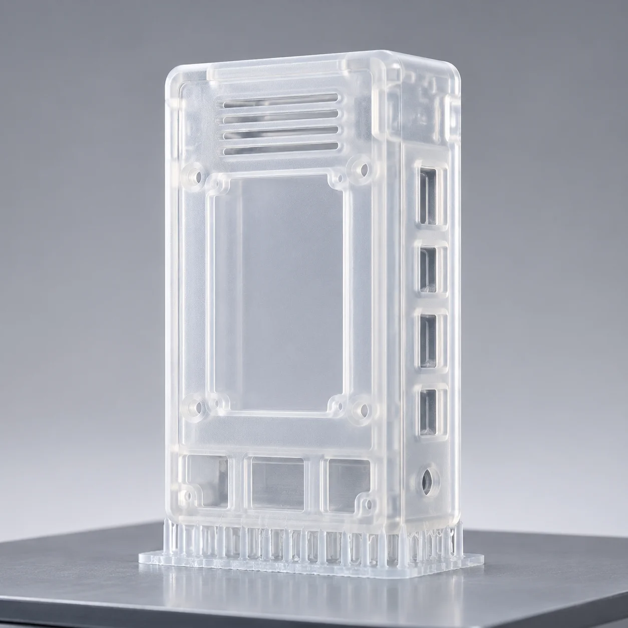
Vertical edge orientation analysis maximizing platform throughput while preventing vacuum cupping on hollow bodies.

Clear Resin • Low
View Setup