Case Protocol #OG-10

Interlocking Parts Support

A rigorous layout blueprint for mechanical interlocking mechanisms, snap hooks, and gear interfaces designed to isolate mating faces from support tip scarring.

November 2026 Assembly Tolerance 6 Min Read

Interference Geometry Analysis

Understanding why mating interfaces fail when SLA support touchpoints intersect critical sliding channels.

Resin: Durable Resin Compound Angle: 32° Pitch / 18° Yaw Complexity: Medium Joint Integrity: Verified Clearance

When two parts are manufactured to fit together directly from the build platform, support scars create unexpected dimensional growth. A standard touchpoint of 0.4 mm leaves an elevated nub after flush cutting, expanding the local perimeter by as much as 0.15 mm. In an assembly engineered with an overall clearance gap of 0.2 mm, this localized protrusion binds the mating channel immediately.

By shifting the orientation so that contact pillars anchor only along non-functional structural chamfers, interlocking faces emerge clean. The Durable Resin formulation provides the low friction coefficient and ductility needed for repetitive snap engagement, while strategic orientation eliminates any requirement for manual reaming or abrasive sanding within the internal tracks.

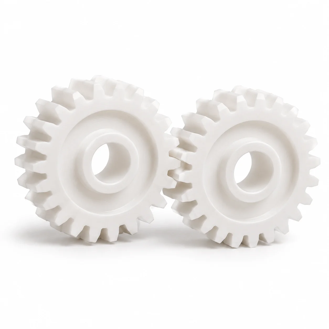
Protected Envelope Visual

Visualizing touchpoint exclusion zones across interlocking teeth and internal bearing grooves.

Interlocking Parts Support
Exclusion Zone Protocol

The layout depicted above demonstrates intentional support clustering along secondary outer rims. All connection gears, dovetails, and reciprocal retaining tabs point upward during slicing. As peeling suction pulls downward against the flexible vat membrane, the mechanical contact surfaces never confront mechanical support detachment shearing.

Tolerance Benchmarks & Specs

Quantitative thresholds established across multi-part additive sliding tests.

Joint Clearance Allowance 0.25 mm ±0.03 mm
Tip Diameter Target 0.35 mm (Medium Taper)
Minimum Exclusion Offset 1.80 mm from Seam
Post-Cure Shrinkage Ratio 0.65% Uniform

Pre-Flight Slicing Verification

Before launching a batch of mating components, slicer inspectors must verify that no algorithmic generation routines have autoplaced struts within internal sliding channels.

  • Define software exclusion zones directly around female socket apertures and dovetail shoulders.
  • Align the compound build angle so resin drains freely away from interior cavities during peel transitions.
  • Select an alternating staggered strut lattice to control dimensional stability along slender locking claws.

Assembly Setup FAQs

Practical answers for calibrating interlocking tolerances and preventing post-cure binding.

Peer Technical Review

Submit your interlocking part geometry for collaborative peer critique and slicing angle inspection.

Examine Assembly Setup

Connect directly with the editorial bench to review critical sliding channels and calculate customized exclusion boundaries.

Complementary Case Protocols

Compare orientation angles and support allocation methods across other functional mechanical components.

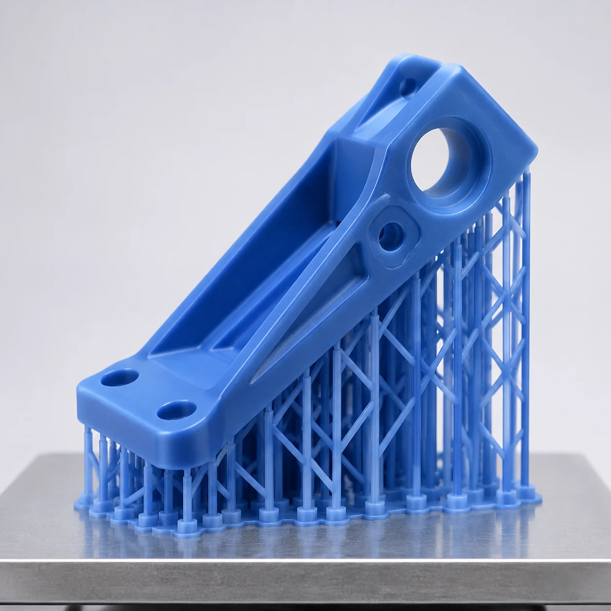
Mechanical Bracket Forty Five Degree Tilt Tough Resin

Mechanical Bracket Forty Five Degree Tilt

Orienting heavy load brackets at 45 degrees to balance peel force reduction with structural support rigidity.

Medium Complexity
View Setup
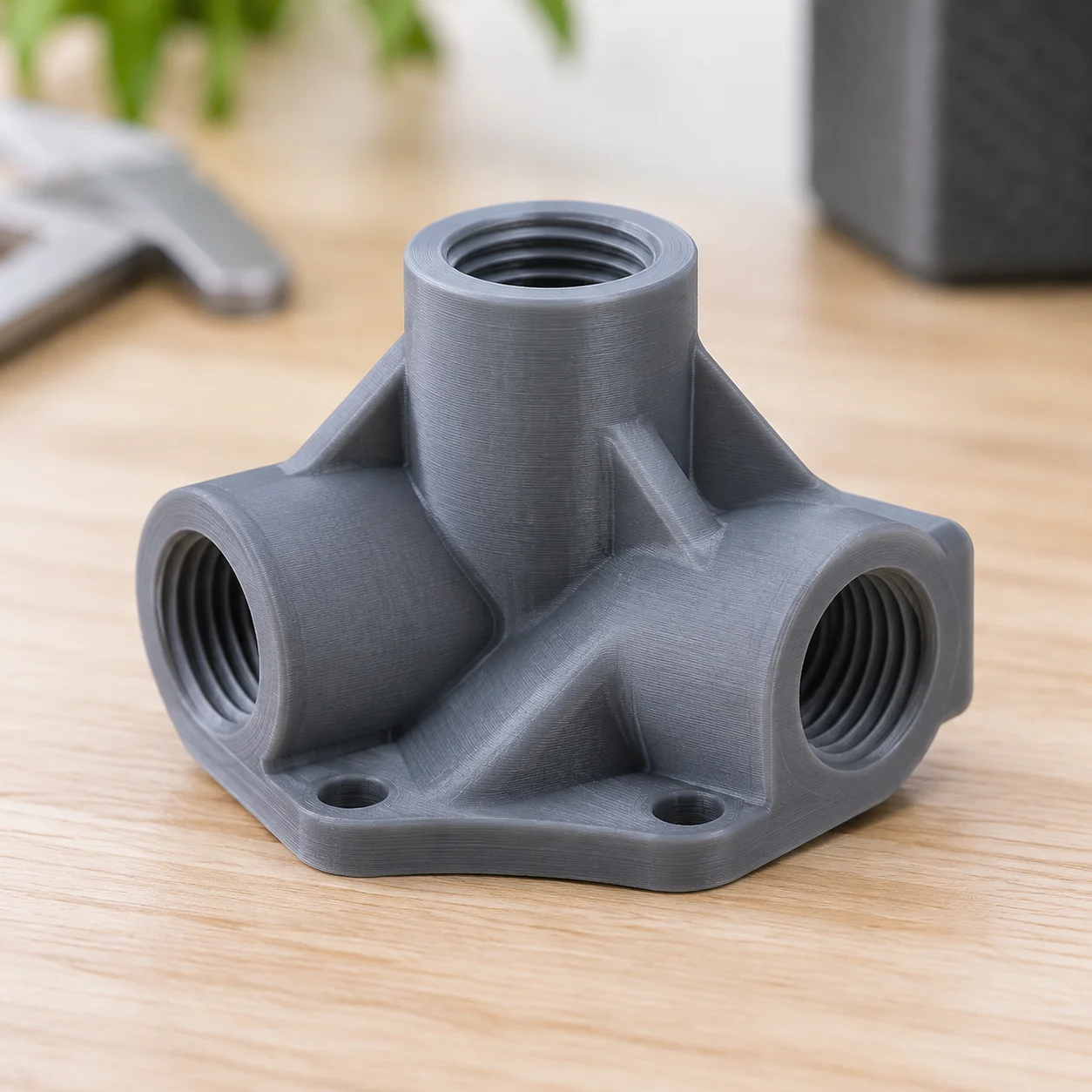
Threaded Hole Orientation Tough Resin

Threaded Hole Orientation

Vertical alignment protocols eliminating internal support material within micro-pitch screw threads.

Medium Complexity
View Setup
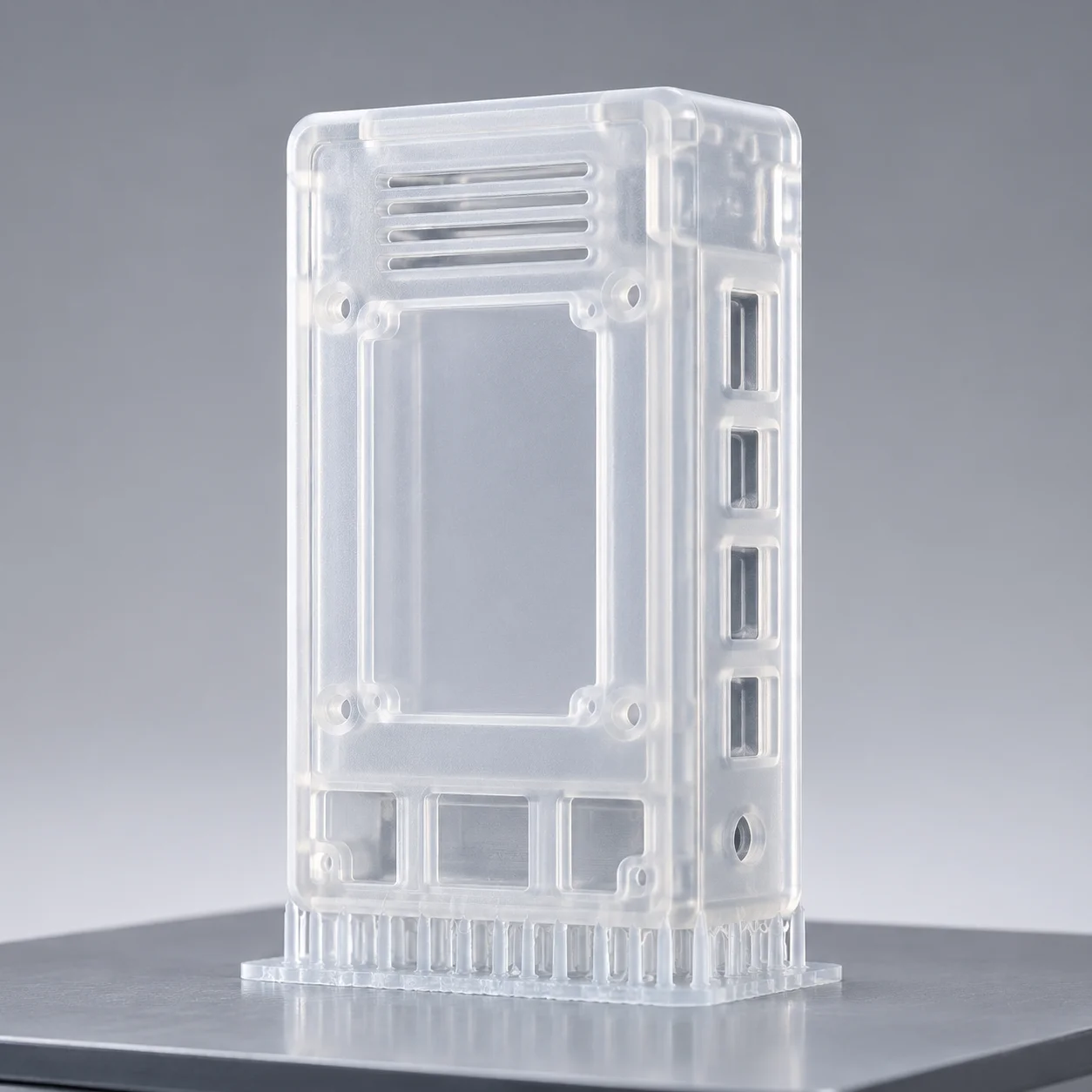
Enclosure Box Vertical Orientation Clear Resin

Enclosure Box Vertical Orientation

Minimizing platform footprint while preserving perimeter snap lips along thin electronic enclosures.

Low Complexity
View Setup