
 Medical
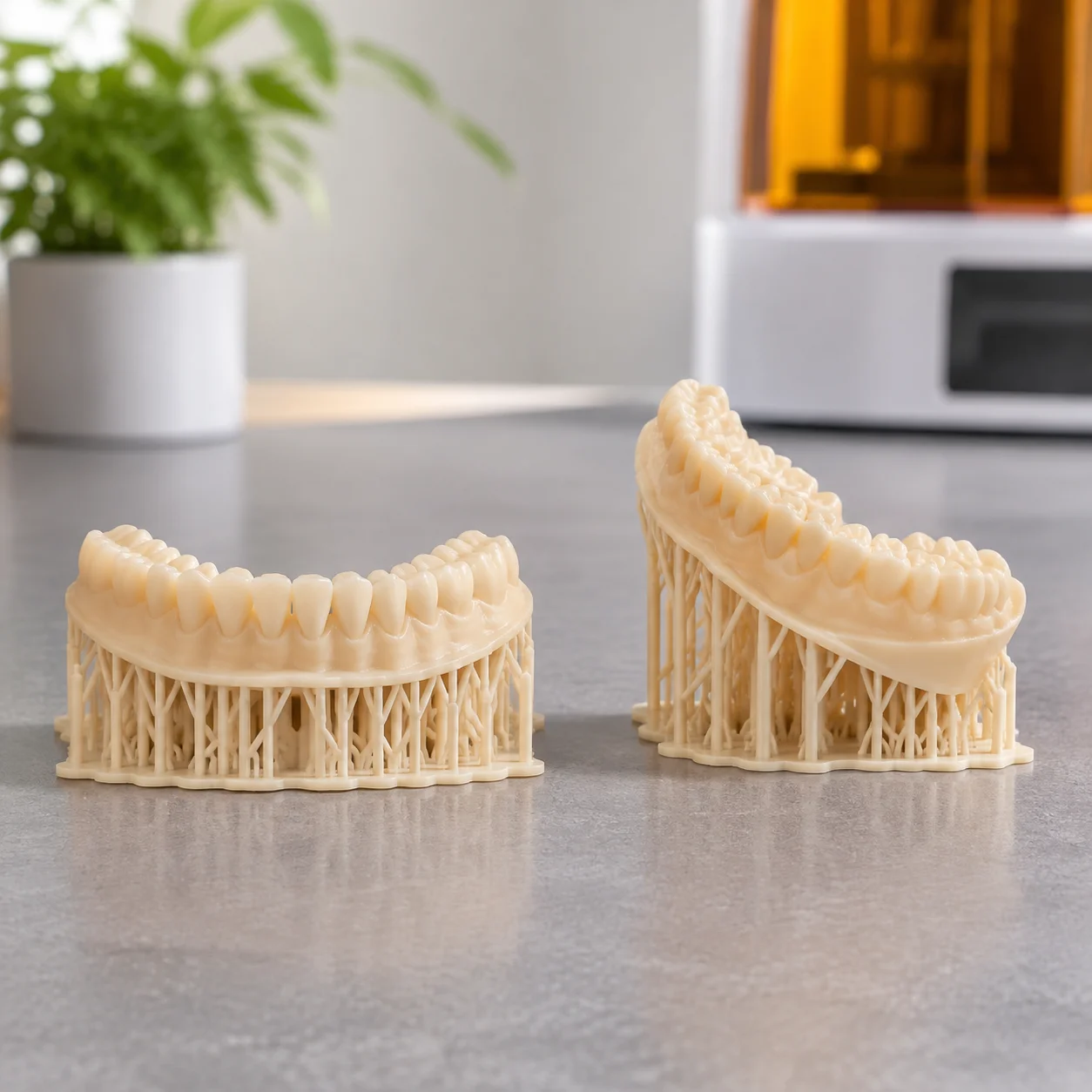
Dental Arch Flat versus Angled
Two 3D printed dental arches comparing flat orientation peel trauma against angled heel support stability.
Model Resin
View Setup
Mitigating cross-sectional peeling delamination and hydrostatic pull by tilting planar geometries between 30 and 45 degrees relative to the vat membrane.
Printing planar faces parallel to the release film produces catastrophic layer separation due to instantaneous peel area shock.
When a flat planar slab prints directly horizontal against the release film, the cross-sectional contact zone expands to the entire boundary footprint at once. During vat peel cycles, this immense surface area induces extreme tensile suction against the fluoropolymer layer. The resulting vacuum load pulls green-state resin apart, causing step lines, severe surface waviness, or outright tearing away from the platform.
By tilting the part across both the lateral X and longitudinal Y axes, the cured surface area per layer reduces to a thin advancing ribbon. This gradual transition distributes tensile mechanical loads evenly, allows fresh resin to replenish the exposure zone smoothly, and prevents localized hydraulic stagnation beneath the workpiece.
Visualizing the cross-sectional area and resin reflow paths under angular elevation.
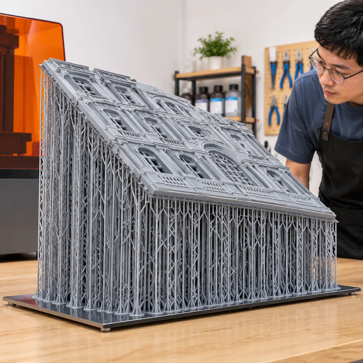
The specimen above illustrates a solid rectangular panel suspended at a 38.5-degree incline with a uniform pillar matrix. Anchoring the initial edge along the trailing side ensures that the peel motion separates the boundary continuously rather than snapping it off simultaneously. Notice how the leading edge maintains a minimal contact strip, permitting the mechanical wiper and resin replenishment currents to flow unhindered across the build zone without generating internal negative pressure pockets.
Balancing peel velocity against volumetric curing density on large format panels.
Rigid flat surfaces demand careful planning around layer shear loads and aesthetic faceting. Follow these validated steps when preparing large geometric panels:
Frequently examined questions regarding plate angling, peel forces, and resin consumption.
Have questions regarding high surface area geometries, thin plates, or structural enclosures?
Submit your parameters for review by our additive manufacturing editorial team. We evaluate peel vectors, cross-section progression, and support footprint density.
Explore adjacent engineering studies on structural balancing and boundary preservation.
Medical
Two 3D printed dental arches comparing flat orientation peel trauma against angled heel support stability.
 Detail
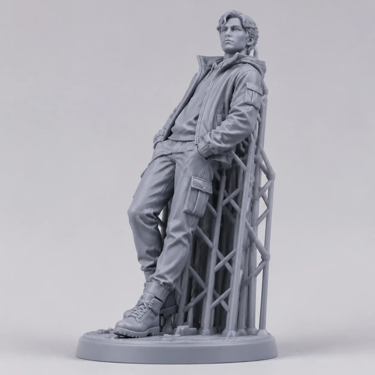
Tabletop character angled backwards to isolate delicate facial geometry completely from contact scarring.
 Housing
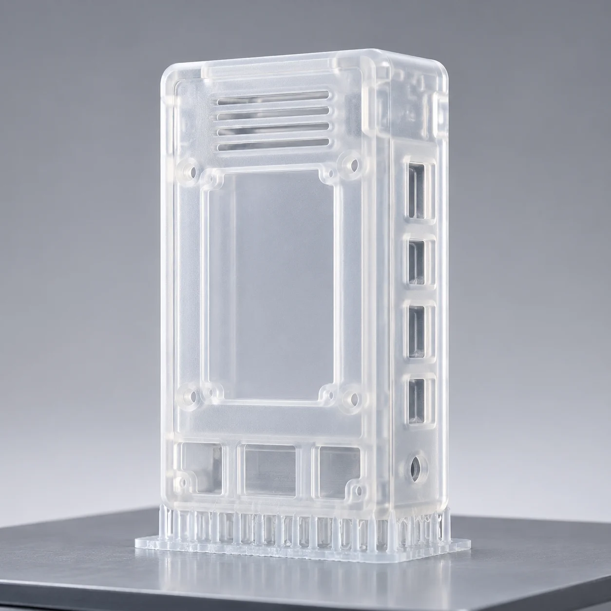
Electronic enclosure box aligned vertically on the build platform to optimize tray occupancy and edge rigidity.