Independent SLA Additive Research

WHERE A SUPPORT TOUCHES,
A DESIGN DECISION
•BEGINS.•

Independent guides to SLA model orientation, support touchpoints, surface priorities, and the tradeoffs behind preparing 3D prints.

Orientation & Peel Stress Vector Analysis
Compromised FaceProtected Surface
Config A — Flat 0° PlaneSevere Suction Risk
BUILD PLATE MAX PEEL FORCE
Tradeoff: Parallel layers generate sudden cross-sectional peel spikes, forcing 22 touchpoints directly onto the visible cosmetic face.
Config B — Angled 42° OffsetProtected Primary Face
BUILD PLATE PROTECTED B-SURFACE
Tradeoff: 35% longer print cycle and added raft mass, but zero support pitting on presentation faces with incremental peel stress.
Tri-Factor Framework

Orientation is a Calculated Compromise

In stereolithography, no single rotation coordinates with every physical objective. Optimizing for pristine cosmetic surfaces introduces support overhead, while stabilizing mechanical anchors demands material and post-processing concessions.

Pillar 01

Surface Appearance

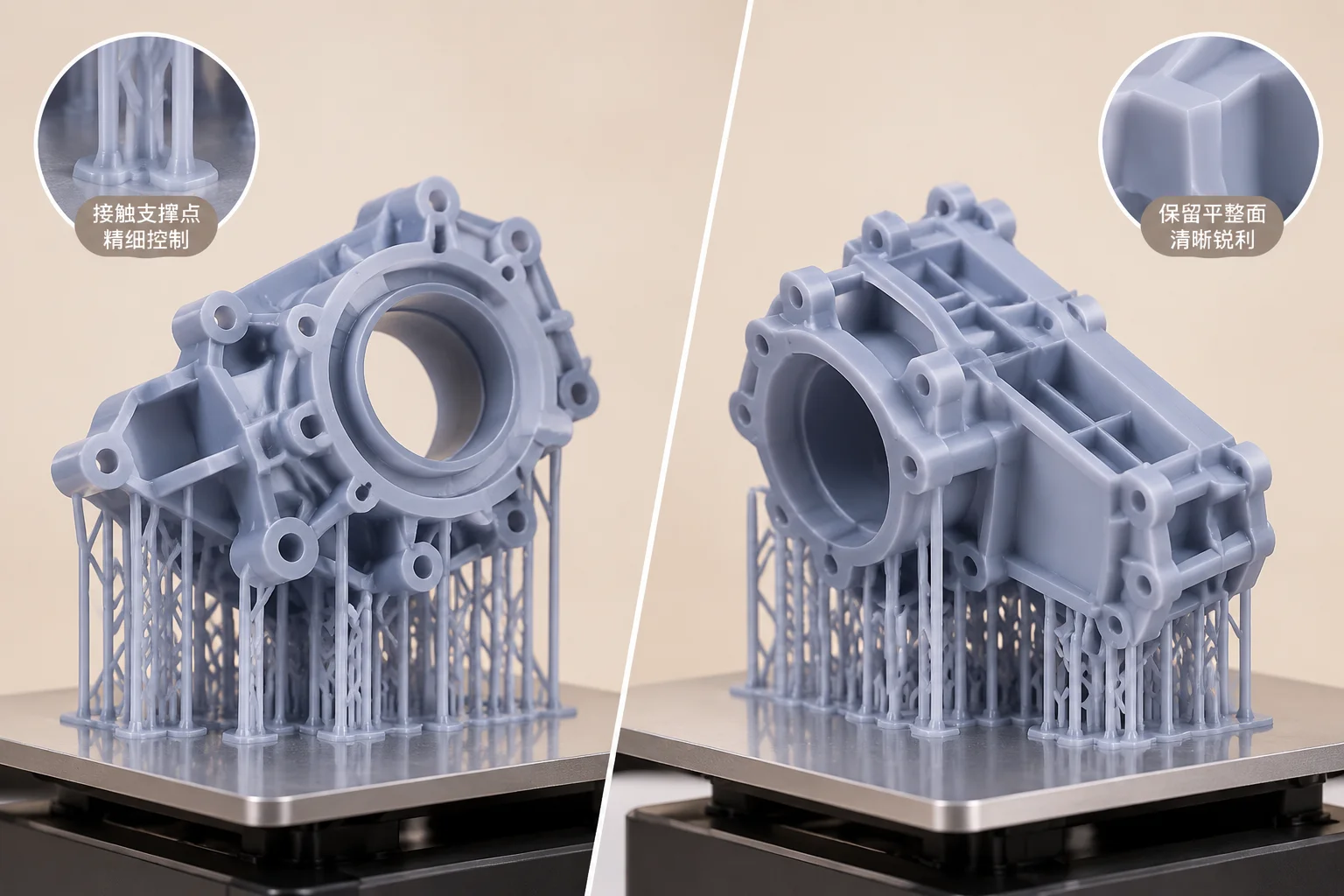
Prioritizes cosmetic sightlines by angling critical visual zones away from the build plate, keeping support contact points isolated to non-functional undercuts.

Cosmetic Shielding Maximum
Contact Pit Risk Relocated
Stair-Step Angle 30° to 45°
Read Analysis
Pillar 02

Model Support

Enforces structural stability against vat peel dynamics and gravitational forces. Scaffolding density is calculated to prevent shear failures and layer shifting.

Anchor Rigidity Heavy Duty
Delamination Guard Reinforced
Post-Process Labor Intensive
Read Analysis
Pillar 03

Print Preparation Context

Harmonizes slice plane height, volumetric resin consumption, and cross-sectional peel velocity to limit cavity suction spikes and build cycle duration.

Suction Spike Venting Optimized
Material Conservation Calibrated
Layer Cycle Speed Balanced
Read Analysis
Technical Inspection

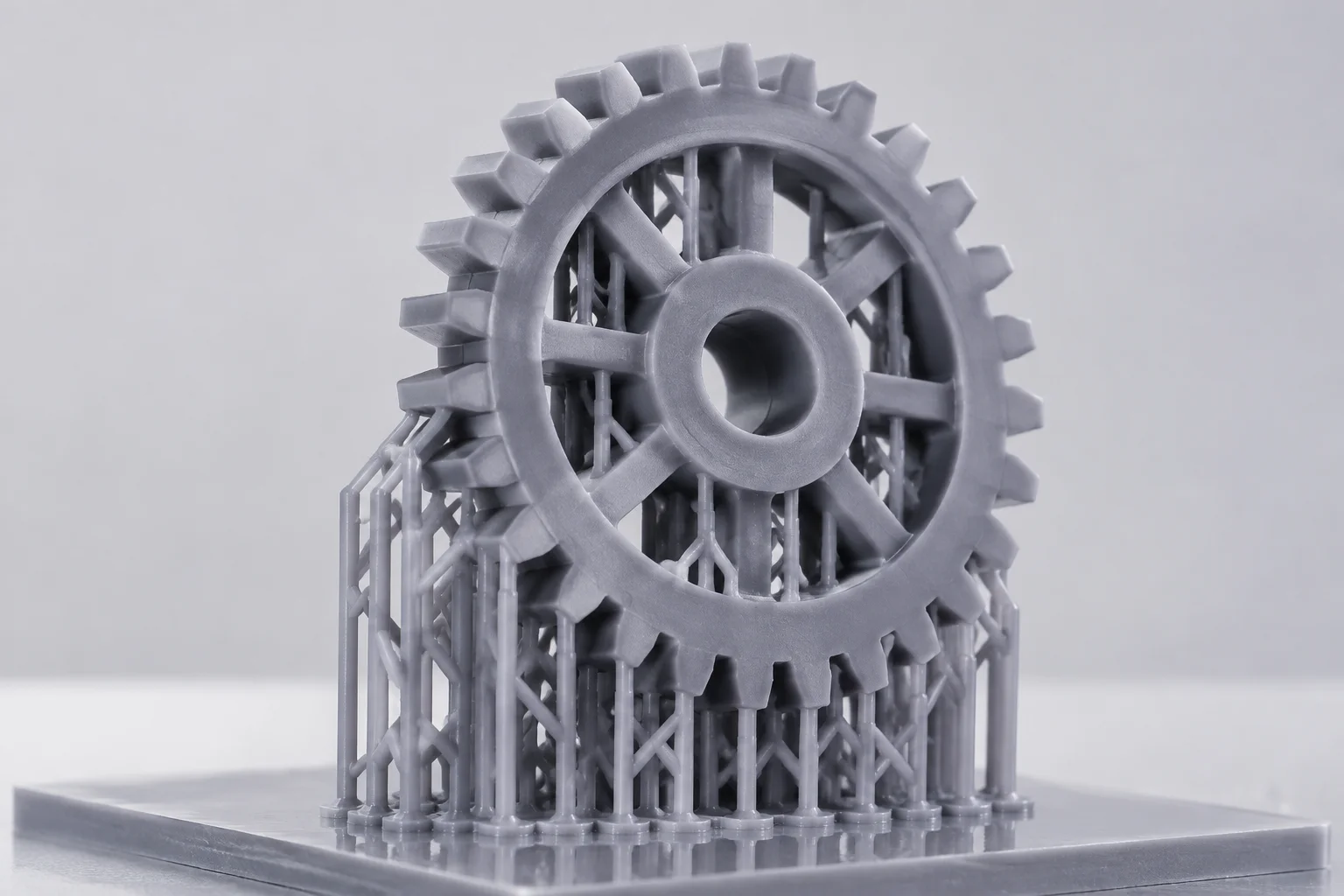
Part Anatomy & Support Footprint Topology

Interactive visual mapping of key structural zones before generating stereolithography lattice anchors. Click zones or buttons below to inspect surface parameters.

SLA Orientation Map
Specimen #45-BRKT
BUILD PLATE 1 2 3 4
Click numbered pins or zones to isolate Build Vector: 38.5° Y-Axis
1

Critical Surface

Zero Marks

Primary aesthetic or sealing face. Support points strictly forbidden here to eliminate pitting, post-cure scar removal, or hand sanding abrasions.

Tolerance: ±0.05 mm Action: Exclude Points
2

Possible Contact Region

Preferred

Non-functional internal undercuts or bottom draft faces where standard density tip touchpoints (0.35 mm – 0.50 mm) cause minimal cosmetic impact.

Density: 0.85 mm Load Rating: Optimal
3

Geometry Requiring Review

Audit

Isolated cantilevered islands and steep overhangs below 30 degrees. Requires manual anchor recalculation or tilt re-orientation to avoid suction delamination.

Island Risk: High Action: Tilt ±12°
4

Post-Processing Access

Clearance

Sufficient channel width for flush cutter blades and UV wash solvent circulation. Ensures quick clipping without gouging neighboring part walls.

Min Gap: 2.8 mm Solvent Wash: Unrestricted
Examine Related Analytical Guides
Explore risk tables and orientation setups from our research desk.
Featured Engineering Study

The Visible Face Support Dilemma

When orienting high-resolution stereolithography parts, engineers face an inevitable compromise: tilt the primary aesthetic surface away from peel vectors or accept localized micropitting. This investigation evaluates identical master geometry manufactured under two opposing mechanical angles.

Setup A: 45° Tilt

Preserves front facade integrity while migrating peeling resistance to non-critical internal facets.

Setup B: Inverted

Minimizes cantilevered overhangs at the expense of manual deburring along primary visible edges.

Comparative orientation analysis for visible face SLA printingDual Angle Matrix
Method:PreForm Peel Stress Log
Material:Standard Rigid Resin
Slicer Telemetry & Diagnostics

PreForm Insider 3.66.0 Geometry Diagnostics & Indicators

Inspect real-time layer transitions, multi-body kinematics, and contact footprints before exposing your vat to laser polymerisation.

Build 3.66.0-rc4 Vulkan Engine Active
Select Diagnostic Layer
Insider Feature Deep Dive

Early Layer Merge (ELM) Geometry Slicer

Telemetry Validated
Raster Layer 001 - 012 TransitionLaser Exposure: Dynamic Ramp
Base Compression
-0.35 mm
Transition Count
8 Layers
Cross-Sectional Peel
14.2 N Avg

Version 3.66.0 introduces an explicit visualizer for the transition zone between over-cured burn-in layers and model geometry. Where previous revisions rendered a uniform solid preview, the new shader shows boundary shifts, helping technicians identify early-stage dimensional swell before sending jobs to the machine.

Dimensional Compensation

Accurately observe the Z-axis elephant foot reduction directly in viewport wireframes.

Build Plate Adhesion

Monitor resin cure gradients across the first 400 microns without trial-and-error exposure.

Documented in Knowledge Base issue #10
Read Technical Paper
Engineering Dispatch

Latest Journal Articles & Field Notes

Consulting & Technical Support

Targeted Engagement Formats for SLA Precision

Compare specialized workflows engineered for print bureaus, dental labs, and individual product creators striving to eradicate surface scarring and uncalculated peel-force failures.

Single Geometry 48h Turnaround

One-off Project

Comprehensive support map audit and peel peel-vector calculation for a single production-critical CAD assembly.

Designed For

Hardware startups, industrial model makers, and short-run production batches.

Core Deliverables

  • Zero-witness contact diameter tuning
  • Suction cup mitigation and vent profiling
  • Pre-sliced verified print profile file
Live 1-on-1 60 Minutes

Single Consultation

Live screen review of challenging CAD files to diagnose recurrent layer separation, cupping, or support pitting.

Designed For

Research engineers, solo creators, and teams troubleshooting specific failures.

Core Deliverables

  • Direct orientation inspection in slicer
  • Peel force vector analysis walkthrough
  • Post-session action plan & parameter sheet
Inquiry & Scheduling

Request Consultation Specifications

Selected format: Production Retainer Support

Interactive Laboratory Workbench

Test SLA Orientation & Support Parameters Live

Simulate peel friction, surface scarring, and suction risks in real time before sending your build file to the vat. Adjust orientation and contact points to inspect the structural balance.

Step 01 / Spatial VectorPart Orientation

45-degree angle distributes peel forces progressively while maintaining critical face integrity.

Step 02 / Contact CalibrationTouchpoint Tip

0.5 mm provides standard anchorage without deep surface pit defects.

Step 03 / Suction Release

Prevents resin pooling and vacuum cup effect.

Interactive Geometry View
Status:Stable Build
VAT BUILD PLATE (Z: 0.00) PEEL TENSION
Peel Force:Moderate (18 N)
Layer Count1,420 Layers
Resin Volume34.2 ml
Scar SeverityControlled
Suction StateVented

Need Lab Review for Intricate Meshes?

Explore full diagnostic risk tools or consult our technical team on critical surface placement.

Technical Overhead Estimator

Quantify Your Workshop Support Friction

Evaluate cumulative manual preparation hours, support scarring corrections, and material consumed by recurring build plate errors prior to pre-print inspection standardization.

Operational Variables

16 plates
2 batches50 batches
25 min / job
5 minutes60 minutes
15 %
0% (stable)40% (high failure)
18 min / job
5 minutes45 minutes

Cumulative Friction Metrics

Monthly Labor Devoted
29.8 hrs

Dedicated entirely to support setup & cleanup.

Quarterly Resin Scrapped
9.4 liters

Lost to build detachment and delaminations.

Annual Reprint Cycles
125 batches

Build platform restarts caused by faulty supports.

Annual Idle Vat Time
358 hrs

Vat cleanup and re-filtration delays.

Data modeled on 250ml average build volumes with typical standard prototyping photopolymers.

Examine Defect Matrix
Press & Citations

Featured in Engineering Publications

Independent technical journals, additive research collectives, and fabrication newsletters analyzing our methodology for stereolithography orientation.

Additive Engineering Review
“SupportFootprint establishes an exceptionally rigorous framework for resin peel dynamics, methodically dismantling the guesswork behind contact diameter calculation.”
Precision Fabrication Weekly
“A refreshing departure from black-box slicer defaults. Their work on angled peel forces and drain hole hydraulics has proven indispensable in high-density production runs.”
Digital Mesh Reports
“Their systematic analysis of cosmetic preservation versus structural stability represents some of the cleanest additive educational writing available today.”

Investigating Real Geometries

Examine our real-world orientation evaluations and critical surface protection logs.